Microstrip patch antenna for high temperature environments

a patch antenna and microstrip technology, applied in the field of patch antennas, can solve the problems of unaddressed industry needs, traditional radome approaches to improving the survivability of patch antennas are not well suited for extended life applications, and patch antennas have not yet been implemented in such harsh environments, so as to improve the performance and reliability of patch antennas, and improve high temperature performance.

Active Publication Date: 2007-02-01
MEGGITT SA
View PDF3 Cites 33 Cited by
  • Summary
  • Abstract
  • Description
  • Claims
  • Application Information

AI Technical Summary

Benefits of technology

[0009] The present invention improves the performance and reliability of a patch antenna within a high temperature environment. The inventive patch antenna includes an antenna radiating element, typically placed within a housing or probe assembly having passages or orifices for distributing air within the housing and to the antenna radiating element. This combination of a patch antenna and housing is useful as a probe for use in measuring characteristics of equipment or devices that operate at a high temperature, typically greater than 600 degrees Fahrenheit. The 600 degrees Fahrenheit. The antenna radiating element typically comprises metallization (or solid metals) in contact with a ceramic, and may have a dielectric window consist

Problems solved by technology

Traditional patch antennas found in consumer, industrial, and military systems are not built of construction methods or materials that can survive a short period of time in such high temperatures, let alone survive and operate reliability for thousands of hours.
Patch antennas have not yet been i

Method used


Image

  • Microstrip patch antenna for high temperature environments
  • Microstrip patch antenna for high temperature environments
  • Microstrip patch antenna for high temperature environments

Examples


Embodiment Construction

[0025] Exemplary embodiments of the present invention provide for a patch antenna capable of operating within a high temperature environment for extended periods of time. For the purpose of this disclosure, a high temperature environment is defined by an environment having a temperature of or greater than 600° F.

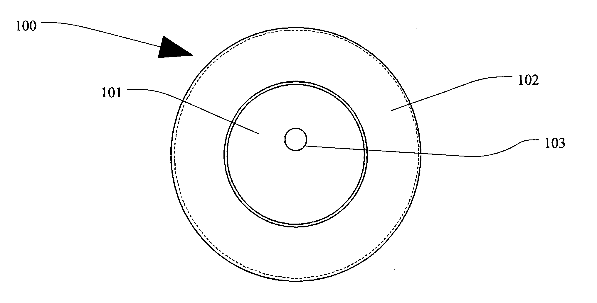
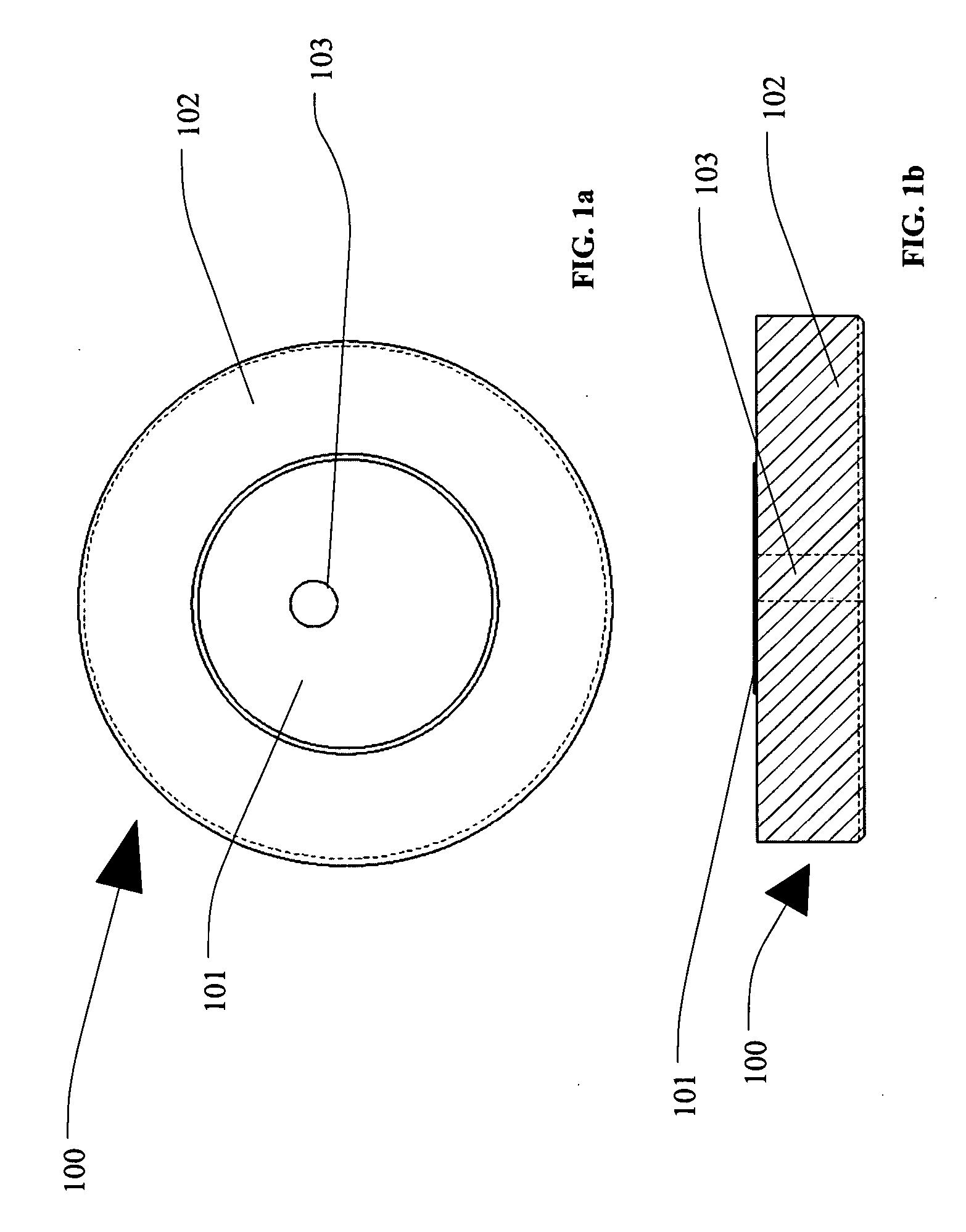
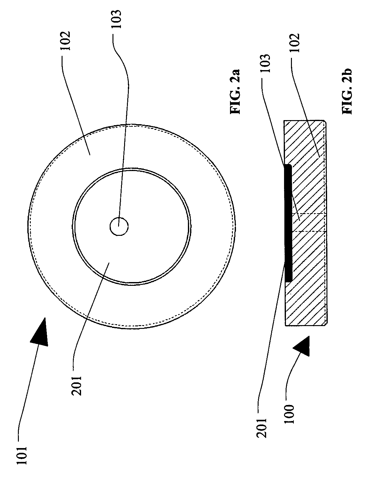
[0026] Exemplary embodiments of the present invention will now be described more fully hereinafter with reference to FIGS. 1-8, in which embodiments of the invention are shown. FIGS. 1-2 provide a schematic of exemplary implementations of patch antennas using different metallization techniques in accordance with one embodiment of the present invention. FIG. 3 provides an assembly drawing of an entire probe assembly without a dielectric window in front of the patch antenna in accordance with one embodiment of the present invention. FIG. 4 provides an assembly drawing of an entire probe assembly with a dielectric window in front of the patch antenna in accordance with one emb...


PUM


Abstract

A patch antenna for operation within a high temperature environment. The patent antenna typically includes an antenna radiating element, a housing and a microwave transmission medium, such as a high temperature microwave cable. The antenna radiating element typically comprises a metallization (or solid metal) element in contact with a dielectric element. The antenna radiating element can include a dielectric window comprising a flame spray coating or a solid dielectric material placed in front of the radiating element. The antenna element is typically inserted into a housing that mechanically captures the antenna and provides a ground plane for the antenna. Orifices or passages can be added to the housing to improve high temperature performance and may direct cooling air for cooling the antenna. The high temperature microwave cable is typically inserted into the housing and attached to the antenna radiator to support the communication of electromagnetic signals between the radiator element and a receiver or transmitter device.

Description

RELATED APPLICATION [0001] Applicants claim priority under 35 U.S.C. 119 to an earlier-filed provisional patent application, U.S. Provisional Patent Application Ser. No. 60 / 652,231 filed on Feb. 11, 2005, entitled “A High Temperature Probe for Displacement Measurements”. The subject matter disclosed by this provisional patent application is fully incorporated within the present application by reference herein.TECHNICAL FIELD [0002] The present invention relates to patch antennas for transmitting and receiving electromagnetic energy and more particularly to the design and use of patch antennas within high temperature environments. BACKGROUND OF INVENTION [0003] Antennas are used to transmit and receive electromagnetic energy. Typically, they are used within ambient temperature environments and are used in such devices as mobile phones, radios, global positioning receivers, and radar systems. Patch antennas, sometimes referred to as microstrip antennas, typically are an antenna design...

Claims


Application Information

Patent Timeline
IPC IPC(8): H01Q1/38
CPCH01Q1/002H01Q1/02H01Q9/0407H01Q1/40H01Q1/42H01Q1/28
Inventor GEISHEIMER, JONATHAN L.BILLINGTON, SCOTT A.BURGESS, DAVIDHOPKINS, GLENN
Owner MEGGITT SA
Why Eureka
Try Eureka