Method and apparatus for cylindrical magnetron sputtering using multiple electron drift paths

a technology of cylindrical magnetron and electron drift path, which is applied in the direction of electrolysis components, vacuum evaporation coatings, coatings, etc., can solve the problems of sputtering rate decline, difficult to simultaneously optimize target utilization and sputtering uniformity, and poor uniformity of film being deposited. to achieve the effect of promoting efficient target utilization

Inactive Publication Date: 2007-04-12
CARDINAL CG
View PDF19 Cites 26 Cited by
  • Summary
  • Abstract
  • Description
  • Claims
  • Application Information

AI Technical Summary

Benefits of technology

[0011] In certain embodiments of the invention, a cathode target assembly for use in sputtering target material onto a substrate includes a generally cylindrical target and a magnetic array, the magnetic array adapted to provide a plasma confinement region adjacent an outer surface of the target comprising a p

Problems solved by technology

As the groove deepens, uniformity of the film being deposited tends to get worse and sputtering rates tend to decline.
Although rotation of the cylindrical magnetron targets improves target utilization, it has been difficult to simultaneously optimize target utilization and sputtering uniformity.
However, the weakened magnetic confinement leads to electron losses and changes in the drift velocity which, in turn, result in spatial variations of plasma density and hence non-uniform sputtering rate.
These effects are not immediately self-correcting and extend well beyond the immed

Method used


Image

  • Method and apparatus for cylindrical magnetron sputtering using multiple electron drift paths
  • Method and apparatus for cylindrical magnetron sputtering using multiple electron drift paths
  • Method and apparatus for cylindrical magnetron sputtering using multiple electron drift paths

Examples


Embodiment Construction

[0030] The following detailed description should be read with reference to the drawings, in which like elements in different drawings are numbered identically. The drawings depict selected embodiments and are not intended to limit the scope of the invention. It will be understood that embodiments shown in the drawings and described below are merely for illustrative purposes, and are not intended to limit the scope of the invention as defined in the claims.

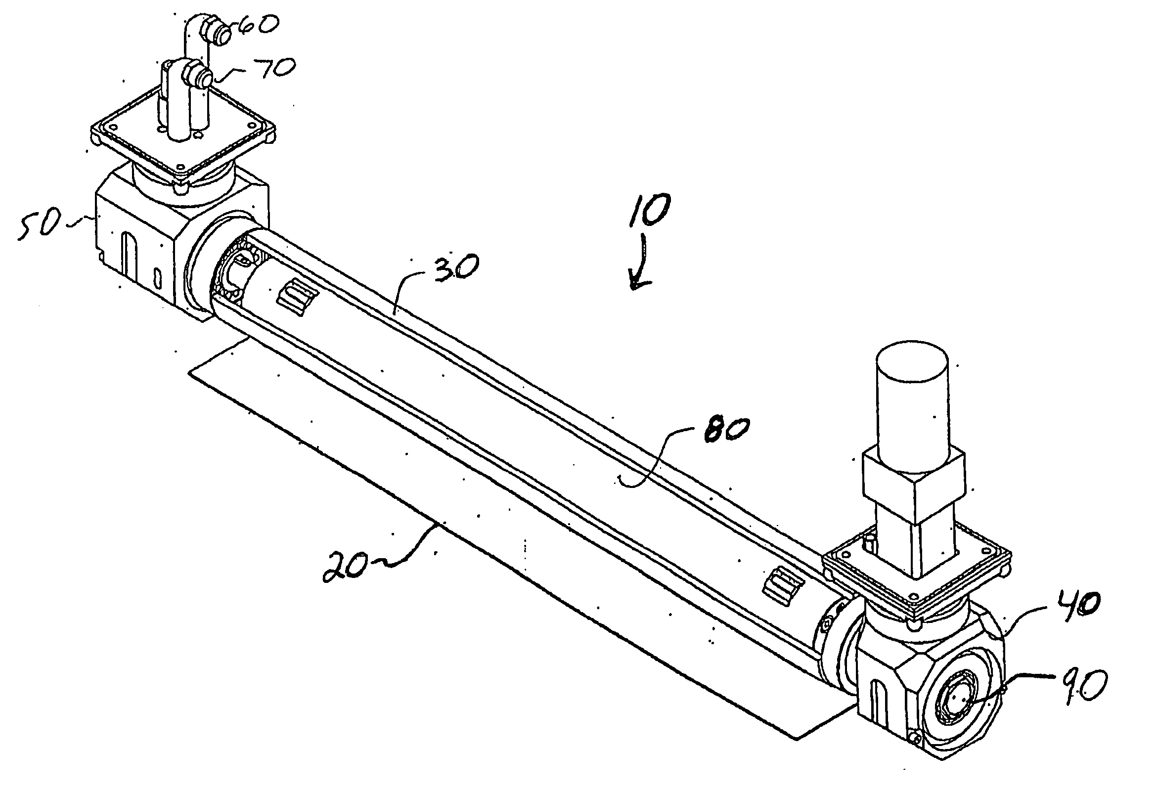
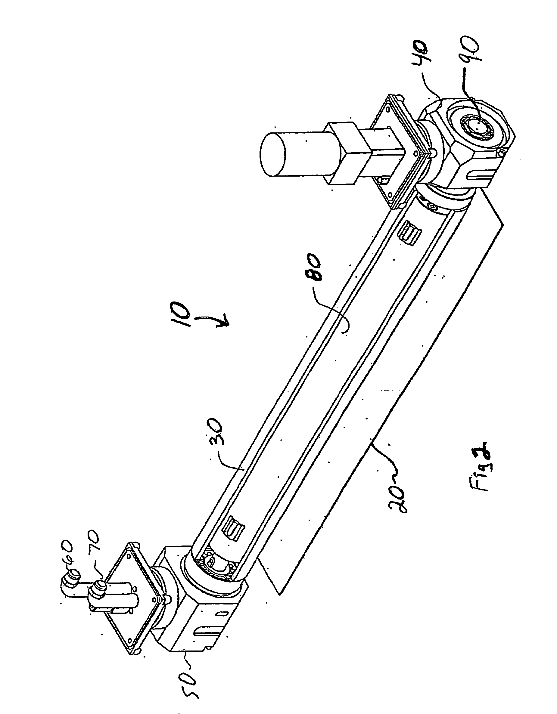
[0031]FIGS. 2 and 3 show a rotatable cathode target assembly in accordance with an embodiment of the present invention. During a sputtering process, the cathode target assembly 10 may be used for coating a substrate 20 with material from a cylindrical target 30 of the assembly. Examples of materials which may form at least part of the cylindrical target 30 and can be sputtered include metals, for example, silver, aluminum, gold, chromium, copper, nickel, zinc, tin, titanium, and niobium. Compounds of various metals, such as nickel...


PUM

PropertyMeasurementUnit
Lengthaaaaaaaaaa
Angleaaaaaaaaaa
Polarityaaaaaaaaaa

Abstract

A cylindrical cathode target assembly for use in sputtering target material onto a substrate comprises a generally cylindrical target, means for rotating the target about its axis during a sputtering operation, a magnetic array carried within the target for generation of a plasma-containing field including a plurality of electron drift paths adjacent an outer surface of the target, and a device for supporting the magnetic array independently of rotation of the target. In certain embodiments of the invention, the magnetic array may include a plurality of magnetic elements arranged to form a plurality of electron drift paths spaced along a substantial length of the target to promote generally uniform film deposition and uniform target utilization along its length.

Description

FIELD OF THE INVENTION [0001] The invention relates to a system and apparatus for depositing films on surfaces, and more particularly to a method and apparatus for reducing or eliminating non-uniformities and variations in deposited film thickness during magnetron sputtering operations. BACKGROUND [0002] A variety of methods exist to apply coatings, such as thin films, to substrates, such as glass. Generally, sputtering is a technique for forming a thin film on a substrate. Sputtering techniques include diode DC sputtering, triode sputtering, and magnetron sputtering. [0003] Magnetron sputtering has become a widely used sputtering technique. Films formed by sputtering can be important for numerous devices, such as semiconductors and window glass. Typical films created by these processes include metallic materials such as silver, aluminum, gold, and tungsten, or dielectric materials such as zinc oxide, tin oxide, titanium oxide, silicon oxide, silicon nitride, and titanium nitride. M...

Claims


Application Information

Patent Timeline
IPC IPC(8): C23C14/32C23C14/00
CPCC23C14/3407C23C14/35H01J37/3405H01J37/342H01J37/3461
Inventor GERMAN, JOHN R.HARTIG, KLAUS H.
Owner CARDINAL CG
Why Eureka
Try Eureka