Optical interferometric pressure sensor

a pressure sensor and optical diaphragm technology, applied in the direction of fluid pressure measurement by mechanical elements, fluid pressure measurement using capacitance variation, instruments, etc., can solve the problem of impairing the sensitive sensor characteristic, unable to achieve sup>mbar with silicon, and even more serious problems

Inactive Publication Date: 2007-04-26
INFICON GMBH
View PDF10 Cites 54 Cited by
  • Summary
  • Abstract
  • Description
  • Claims
  • Application Information

AI Technical Summary

Benefits of technology

[0045] The inventive ODG—sensor arrangement has its base in the CDG sensor made of alumina. Basically this alumina sensor concept is further development to allow optical readout of the mem

Problems solved by technology

However, in vacuum applications pressure sensors of this type are normally usable only for higher pressures in the range of approx.
High resolution at pressures below 10−1 mbar is no longer achievable with silicon.
One of the reasons for this is that the silicon surface reacts with the environment which impairs the sensitive sensor characteristic.
The problem becomes even more serious when the sensor is used in chemically aggressive atmospheres.
Such measures are costly and in the case of mechanically deformable parts such as membranes have only limited success, in particular in highly aggressive media such as fluorine, bromic acid and their compounds which are typically used in vacuum etching processes.
Such thin membranes are very difficult to manufacture and after the sinter step require at least one additional smoothing step.
Cutting or scoring of the green body requires particular care that no dislocations or warping against the surfaces of the future ceramic membrane occur as this also influences the degree of surface unevenness.
In this condition the membrane cannot b

Method used


Image

  • Optical interferometric pressure sensor
  • Optical interferometric pressure sensor
  • Optical interferometric pressure sensor

Examples


Embodiment Construction

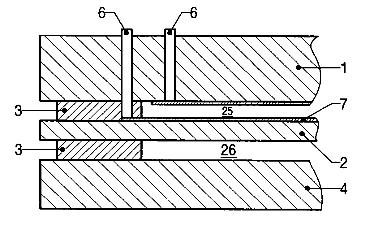
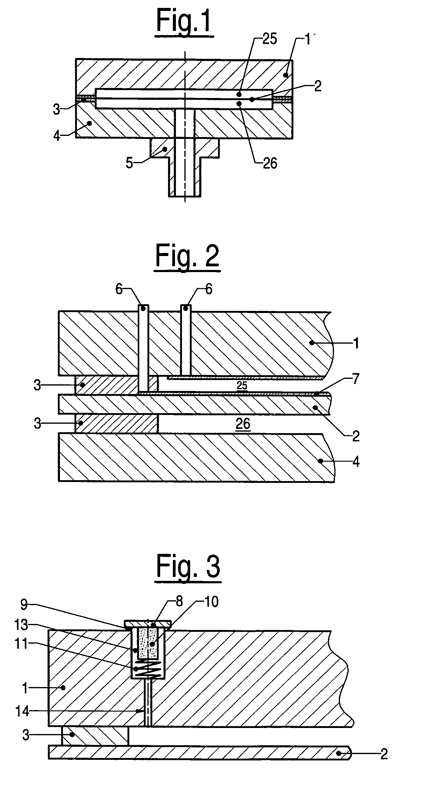
[0058] The preferred inventive arrangement of an ODG (Optical Diaphragm Measuring Cell) measuring cell made of Al2O3 with a structure essentially symmetrical about the membrane is illustrated by the cross-section in FIG. 10. The first housing (1) consists of a ceramic plate made of Al2O3 which along its edges is tightly bonded at a distance of 2 μm to 50 μm relative to the ceramic 2 and which encloses a reference vacuum chamber 25. The distance between the two surfaces is usually established directly during the assembly by means of the sealing material 3, 3′ located between the membrane edge and the housing. In this way a completely plane housing plate 1 can be used. In the same way a measurement vacuum chamber 26 is formed in a second housing 4 on the opposite membrane side; this vacuum chamber is accessible for the media to be measured via a connecting port 5 through an opening in the housing 4.

[0059] The seal 3, 3′ on both sides of the membrane 2 defines, as mentioned above, the...


PUM

PropertyMeasurementUnit
Grain sizeaaaaaaaaaa
Temperatureaaaaaaaaaa

Abstract

A capacitive vacuum measuring cell has a first housing body and a membrane, both of Al2O3 ceramic or sapphire. The membrane is planar with a peripheral edge joined by a first seal to the first housing body to form a reference vacuum chamber. A second housing body of Al2O3 ceramic or sapphire opposite the membrane, is joined to the peripheral edge of the membrane by a second seal to form a measurement vacuum chamber. A port connects the vacuum measuring cell to a medium to be measured. At least in the central area of the first housing body, an optical transparent window is formed and at least the central region of the membrane has an optically reflective surface. Outside the reference vacuum chamber, in opposition to and at a distance from the window, an optical fibre is arranged for feeding in and out light onto the surface of the membrane.

Description

INCORPORATION BY REFERENCE [0001] The present application claims priority under 35 U.S.C. 119(e) to U.S. Provisional Application No. 60 / 707,770 filed on Aug. 12, 2005, which is incorporated here by reference.FIELD OF THE INVENTION [0002] The invention relates to a optical diaphragm gauge for measuring high vacuum pressure in a wide pressure range. DESCRIPTION OF THE RELATED ART [0003] Semiconductor industry manufactures semiconductor parts using among other techniques chemical vapor deposition (CVD), physical vapor deposition (PVD), implant and (dry) etch processes. Typical pressure ranges of process in the semiconductor industry and pressure ranges of vacuum gauges are shown in FIG. 1a. As shown in FIG. 1a those processes operate typically from 10−4 to 10 mbar. Typical process gauges for these applications are capacitance diaphragm gauges. [0004] The market demand for high-temperature diaphragm gauges is expected to grow in the coming years mainly due to the introduction of atomic ...

Claims


Application Information

Patent Timeline
IPC IPC(8): G01L9/12
CPCG01L9/0079Y10T29/49776Y10T29/49769G01L11/00G01L11/02
Inventor WALCHLI, URSBJORKMAN, PERSAARI, HEIKKIANTILA, JARKKOHANSELMANN, HANSJAKOBWUEST, MARTIN
Owner INFICON GMBH
Why Eureka
Try Eureka