Phased array antenna with extended resonance power divider/phase shifter circuit

Active Publication Date: 2007-04-26
THE RGT OF THE UNIV OF MICHIGAN
View PDF5 Cites 27 Cited by
  • Summary
  • Abstract
  • Description
  • Claims
  • Application Information

AI Technical Summary

Benefits of technology

[0005] In the present invention, a new phased array technique based on the extended resonance power dividing method is disclosed. The extended resonance is a power dividing combining technique, which results in a very compact circuit structure wit

Problems solved by technology

This approach eliminates the need for separate power splitter and phase shifters in a conventional phased array system, resulting in significant amount of reduction in the circuit complexity and cost.
Also, phased arrays based on this technique are compact and have simple circuit structures.
It should be noted that the present technique has some performance limitations.
Also, the scanning range for the simplest design case is limited to approximately +/−22 degrees, whereas conventional systems can go up t

Method used


Image

  • Phased array antenna with extended resonance power divider/phase shifter circuit
  • Phased array antenna with extended resonance power divider/phase shifter circuit
  • Phased array antenna with extended resonance power divider/phase shifter circuit

Examples


example 1

[0049] To demonstrate the operation of this technique, a two GHz extended resonance based phased array including four edge coupled microstrip patch antennas placed half wavelength apart was designed, fabricated and tested. A 31 mil thick RT / duroid 5880 substrate from Rogers Corporation was used to build the phased array. MSV34 series chip varactor diodes from Metelics Inc. were used as tunable capacitors. A photo of the phased array can be seen in FIG. 7. The overall size of the phased array was 39×25 cm2. The measured H-plane pattern of the phased array for various diode voltages is shown in FIG. 8 and the measured performance is summarized in Table 1. The results show that the phased array can scan the beam + / −13.5 degrees with the application of 2 V to 30 V reverse bias to the varactor diodes. The side lobe level was better than 7 dB. The gain of the phased array was measured to be 8.3 dB at 30 V reverse bias applied to the varactors. It can be seen from FIG. 8 that the gain at 2...

example 2

[0057] A 10 GHz extended resonance based phased array including 8 microstrip patch antennas has been designed, fabricated and tested. The antennas were half wavelength apart. A 15 mil thick TMM3 substrate from Rogers Corporation was used to build the phased array. MA46580 series beam lead varactor diodes from MACOM Inc. were used as tunable capacitors. A photo of the phased array is shown in FIG. 9. The overall size of the phased array was 11.4×3 cm2 (except for the bias lines and input feed line). The measured H-plane pattern of the phased array for various diode voltages is shown in FIG. 10. The preliminary measurement results show that the phased array can steer the beam 18 degrees with the application of 2.25 V to 10.2 V reverse bias to the varactor diodes. The measured side lobe level was better than 10 dB. It can be seen from FIG. 10 that the gain of the phased array decreases as the diode voltage is reduced to 2.25 V. This is due to the low quality factor of the varactor diod...

example 3

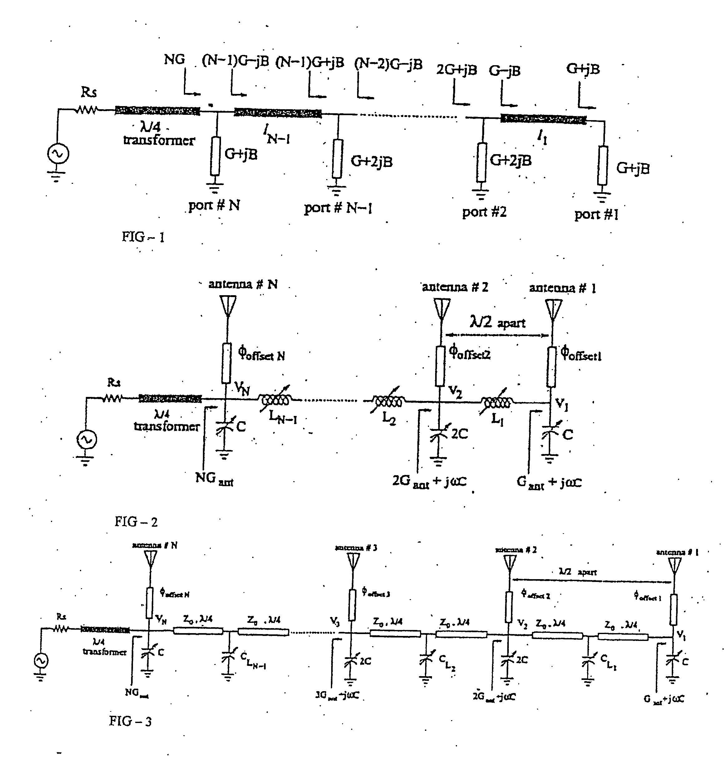
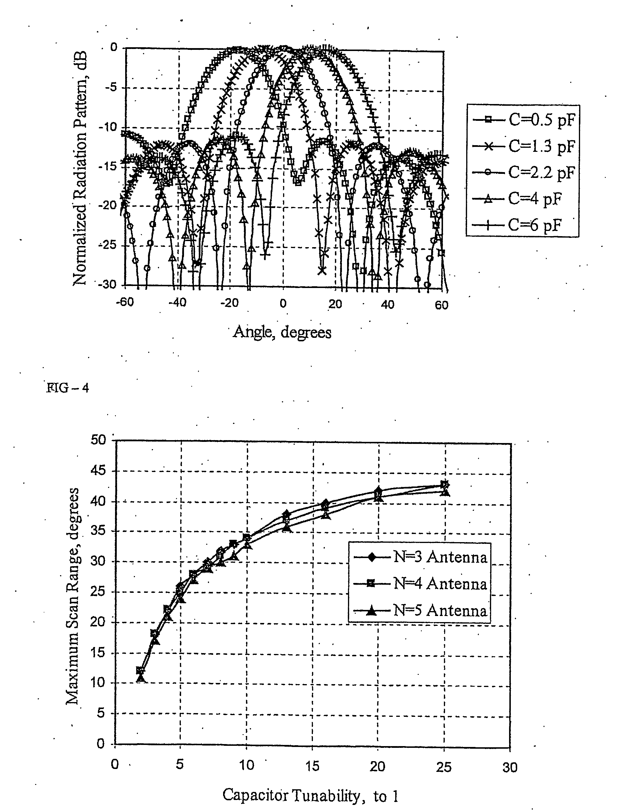
[0063] Based on the theory outlined, simulated array factor for a 4-antenna extended resonance phased array for various normalized capacitive susceptances is shown in FIG. 18 (antennas are λ / 2 apart). The simulated scan range is 21 degrees for the varactor tunability of 3.2:1. In this simulation, the varactors and transmission lines were assumed to be lossless. The effect of finite varactor quality factor (Q) on the efficiency of the extended resonance array feed has also been studied. The equivalent circuit model for the varactor is shown in FIG. 19 and its associated quality factor is given in equation (17). Q=ω⁢ ⁢CGC(17)

[0064] Therefore, at the power divider ports, some portion of the divided power is radiated through the antenna with input conductance of Gant, and the rest is dissipated within the varactors through their shunt conductances. Assuming all the varactors in the circuit have the same quality factor, the efficiency of the extended resonance phased array feed can be c...


PUM


Abstract

A phased array for generating a directed radiation pattern includes a plurality of power divider ports, a first tunable element connected in series between each pair of adjacent power divider ports, an antenna connected to each of the power divider ports, and a second tunable element connected in parallel with each antenna The phased array can include equal phase differences between successive power divider ports, equal amplitude of the signal at each antenna, an equal amount of successive phase change in a signal at each antenna, a source connectible to at least one power divider port including an alternating power supply through a quarter-wave transformer, the first tunable element being either an inductor or a capacitor, the second tunable element being either an inductor or a capacitor, and/or each antenna separated by a successive antenna by a half wavelength.

Description

CROSS-REFERENCE TO RELATED APPLICATIONS [0001] This application claims the benefit of U.S. Provisional Patent Application Ser. No. 60 / 472,607 filed May 22, 2003, which is incorporated by reference herein in it's entirety.FIELD OF THE INVENTION [0002] The present invention relates to an extended resonance based phased array system for reducing and / or eliminating the need of a separate power splitter and phase shifter in a conventional phased array system, which results in a very compact and simple circuit structure at lower-cost. BACKGROUND OF THE INVENTION [0003] A phased array is a group of antennas in which the relative phases of the respective signals feeding the antennas are varied in such a way that the effective radiation pattern of the array is reinforced in a desired direction and suppressed in undesired directions. Phased arrays are extensively used in satellite communications, multipoint communications, radar systems, early warning and missile defense systems, etc., so the...

Claims


Application Information

Patent Timeline
IPC IPC(8): H01Q1/50H01QH01Q3/26H01Q21/08H04M11/00
CPCH01Q3/26H01Q3/34H01Q21/08
Inventor MORTAZAWI, AMIRTOMBAK, ALI
Owner THE RGT OF THE UNIV OF MICHIGAN
Why Eureka
Try Eureka