Embedded electrode conformations for balanced energy, power, and cost in an alkaline cell

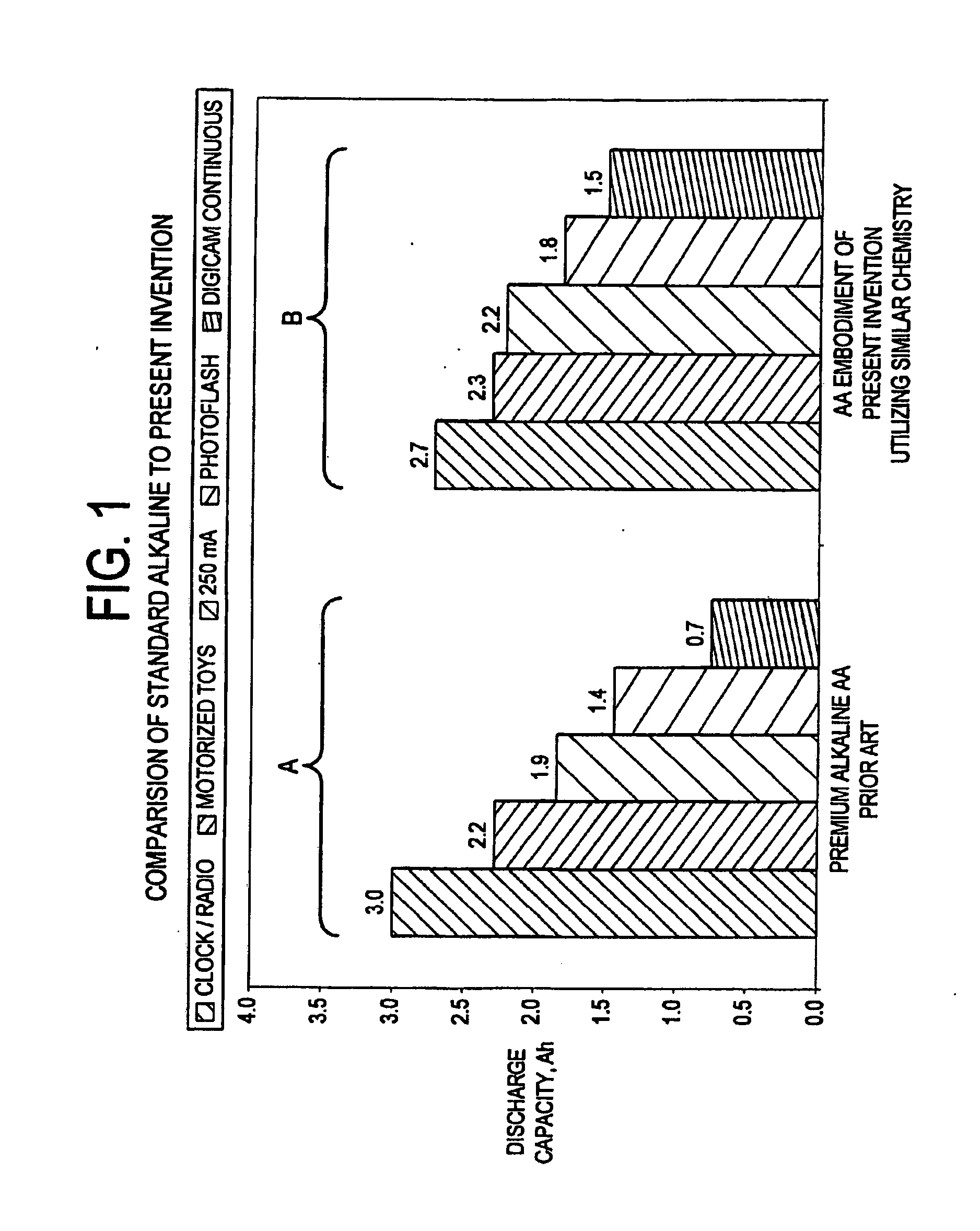
a technology of alkaline cells and conformations, applied in the field of electrochemical battery cells, can solve the problems of inefficiency under high rate discharge, power consumption of many new devices that require higher continuous or pulse currents, and insufficient efficiency of conventional or even premium alkaline cell designs to efficiently deliver stored energy at the higher drain rate, etc., to achieve the effect of reducing the number of emitted electrodes, and increasing energy capacity

Inactive Publication Date: 2007-04-26
RECHARGEABLE BATTERY CORP
View PDF25 Cites 12 Cited by
  • Summary
  • Abstract
  • Description
  • Claims
  • Application Information

AI Technical Summary

Benefits of technology

[0035] The methods of manufacturing an electrochemical battery cell in accordance with the principles of the present invention can be readily translated to automated high-speed production. One or more steps of these methods can be envisioned as replacing certain unit operations in a conventional bobbin cell manufacturing plant, with others being similar to those for conventional bobbin manufacturing, while maintaining equivalent throughputrates.
[0036] In addition a novel formulation of nickel oxy-hydroxide (NiOOH) is proposed in view of an associated method of formulating the NiOOH compound for use with an electrochemical battery cell. Cells made with the novel NiOOH formulation were found to provide increased energy capacity greater than known NiOOH cells produced under conventional methods. The formulation is derived from oxidation of nickel hydroxide using sodium hypochlorite solution without the presence of an alkaline hydroxide (e.g., lithium, sodium or potassium hydroxide). Without the presence of the alkaline hydroxide environment, the NiOOH material has been found to have superior performance when utilized in an electrochemical battery cell.
[0037] When utilized in a particular battery cell configuration as described herein, the above-described NiOOH formulation provides both increased response to energy demands and is of relatively low cost. Also the NiOOH electrodes made according to the present invention are more easily manufactured. This particular electrochemical battery cell has a simple and low cost construction with power and energy capacities comparable to more complex and more costly battery cell constructions.

Problems solved by technology

Compared to earlier devices, such as, for example, transistor radios, the power consumption for many of these new devices can require higher continuous or pulse currents.
Conventional or even premium alkaline cell designs cannot efficiently deliver their stored energy at the higher drain rates.
These inefficiencies under high rate discharge are related to internal resistance and electrochemical limitations of the conventional alkaline bobbin-cell construction.
While the bobbin cell construction is a simple design that allows for high-speed, low-cost manufacturing, the surface area between the anode and cathode in a conventional bobbin cell is limited to the geometrical surface area of the cylinder of separator between the anode and cathode.
The greater interfacial area comes at the expense of additional complexity and cost to manufacture.
Spiral winding requires precision alignment of anode, cathode, and separator, with lower production rates and higher capital equipment costs than “bobbin” construction cells.
Another trade-off of the spiral wound design is the higher amount of separator and current collector required, which take up volume that could otherwise be utilized for active material.
Thus, while converting from a bobbin design to spiral wound design increases the inter-electrode surface area and power capability, it also reduces the energy content of the cell.
More costly spirally wound batteries may be over designed for many portable applications.
All of these design strategies have limitations in the effective increase in surface area that is possible and introduce additional complexities that detract from the utilitarian design of the conventional bobbin cell.
Some may achieve greater surface area but at the sacrifice of a cell balance change that decreases the energy content.
The more complex geometries may introduce orientation requirements and the need for more complex tooling and machinery for assembly.
Complex geometries can make it difficult to apply separator uniformly and consistently especially in high-speed production, and may necessitate unconventional approaches such as internally applied conformal coatings.
For example, branched or lobed designs have limited ability to increase surface area unless the lobes are made thinner which makes applying separator and filling uniformly with gelled anode more difficult.
If the lobes or branches are not thinner and longer then not much increase in surface is provided and the cell balance may be changed to be less efficient due to changes in relative cross-sectional area of the anode and cathode structures.
Alignment of cathode pellets and breakage of pellets in lobed designs could make manufacture difficult.
Thus, such designs do not address the aforementioned power characteristic problems.
Both of these methods, however, are more complex and costly to produce than a simple bobbin cell.
However, the prismatic form is not as effective at accommodating internal pressure and non-uniform bulging may occur with maximum deflections at the midpoint of the long wall spans.
While increasing the wall thickness of the container can prevent bulging of the container, this also reduces the internal volume available for active electrode masses.

Method used


Image

  • Embedded electrode conformations for balanced energy, power, and cost in an alkaline cell
  • Embedded electrode conformations for balanced energy, power, and cost in an alkaline cell
  • Embedded electrode conformations for balanced energy, power, and cost in an alkaline cell

Examples


example 1

[0117] This is an example of the “embedded corrugated-fold” design as shown in FIGS. 5A-5D. In this example, a porous solid electroformed zinc is utilized as the anode. Referring generally to FIGS. 8-11 for all of the examples, a planar electroformed zinc is utilized as an anode sub-assembly 51 of approximately 1.5″ W×1.625″ H. The electroformed zinc anode sub-assembly 51 was formed by pasting a zinc oxide / binder slurry 63 onto a thin metal substrate 64 of silver or copper with an attached insulated lead 62 and then electroforming in an alkaline bath. The anode sub-assembly 51 was then washed and dried, and heat-sealed in a pouch of Scimat 700 / 70 separator 52 to form an anode assembly 55. The anode used was approximately 4.7 g in the dry state and 0.045 inches dry thickness including substrate and lead. The dry anode assembly 55 was soaked in 9 N KOH for at least one hour prior to being folded into a loose corrugated “W” shape 53. Two planar MnO2 cathodes coated onto a perforated me...

example 2

[0118] This example illustrates the “embedded corrugated-fold” design shown in FIGS. 5A-5D, specifically utilizing pasted zinc in an anode sub-assembly. This anode is fabricated from zinc powder using an extrusion or pasting process to form an anode sheet. The anode sub-assembly was prepared by mixing powdered metallic zinc or zinc alloys and zinc oxide together with a Kraton binder and Shellsol solvent. The mixture was pasted onto a 0.002 inches thick perforated copper foil substrate with an attached lead and the solvent was allowed to evaporate. The sub-assembly was then wrapped in an SM700 / 70 separator to form the anode assembly. The dry anode assembly was soaked in 9 N KOH for at least one hour prior to being folded into a loose corrugated “W” shape. Two planar MnO2 cathodes coated onto a perforated metal substrate and with an overlay of 9 N KOH soaked KC16 absorber were placed, such that one was on each side of the anode and folded to conform as intermeshing “W's.” The corrugat...

example 3

[0119] This example illustrates the “embedded corrugated-fold” design shown in FIGS. 5A-5D utilizing zinc gel to form the anode assembly. The zinc gel comprised powdered metallic zinc or zinc alloys and optionally zinc oxide together with a suitable gelling agent such as carboxymethyl cellulose, polyacrylic acid, starches, and their derivatives. An anode current collector with an attached lead was placed in a pouch prepared out of the Scimat SM700 / 79 separator and 7 g of the gel was added into the pouch which was then heat sealed at the bottom to form the anode assembly. Two planar MnO2 cathodes coated onto a perforated metal substrate and with an overlay of 9 N KOH soaked KC16 absorber were placed, such that one was on each side of the anode assembly and folded to conform as intermeshing “W's.” The corrugated stack was pressed and molded into a cylindrical shape in a compression die with a 0.500 inch to 0.515 inch diameter bore prior to insertion into the housing or can. The thickn...


PUM

PropertyMeasurementUnit
voltageaaaaaaaaaa
diameteraaaaaaaaaa
thicknessaaaaaaaaaa

Abstract

A battery cell, such as a cylindrical or prismatic alkaline cell, is disclosed having significantly improved capacity utilization at mid-range power levels of discharge by implementing a curvilinear-like inner electrode configuration that provides moderated surface area between the inner and outer electrodes as compared to high-power discharge applications utilizing a densely corrugated geometry for the inner electrode. A battery cell, such as a cylindrical or prismatic alkaline cell, having a curvilinear-like inner electrode configuration that provides moderated surface area between the inner and an NiOOH outer electrodes. The NiOOH material made from a nickel hydroxide reacted with a hypochlorite in the absence of an alkaline hydroxide

Description

CROSS-REFERENCE TO RELATED APPLICATIONS [0001] This application claims priority to Provisional Application 60 / 718,406 filed Sep. 19, 2005 and is a continuation-in-part of U.S. patent application Ser. No. 10 / 904,097, filed Oct. 22, 2004, which is a continuation-in-part of U.S. patent application Ser. No. 10 / 710,135, filed Jun. 21, 2004, which is a continuation-in-part of U.S. patent application Ser. No. 10 / 710,116, filed Jun. 18, 2004, which is a continuation-in-part of U.S. patent application Ser. No. 10 / 846,020, filed May 14, 2004, which claims priority to Provisional Application Ser. No. 60 / 499,545, filed on Sep. 2, 2003; Provisional Application Ser. No. 60 / 503,298, filed Sep. 16, 2003; and Provisional Application Ser. No. 60 / 513,167, filed Oct. 21, 2003, all of which are incorporated herein by reference.TECHNICAL FIELD [0002] The present invention generally relates to electrochemical battery cells. More particularly, the invention relates to electrochemical battery cells, such as...

Claims


Application Information

Patent Timeline
Patent Type & Authority Applications(United States)
IPC IPC(8): H01M2/02H01M4/52H01M10/04H01M4/02H01M50/107H01M50/431H01M50/449H01M50/463H01M50/533H01M50/538
CPCH01M2/0202Y10T29/49115H01M2/022H01M2/162H01M2/1646H01M2/1666H01M2/18H01M2/263H01M4/043H01M4/06H01M4/08H01M4/244H01M4/26H01M4/42H01M4/50H01M4/52H01M4/70H01M4/78H01M6/04H01M6/08H01M6/10H01M10/04H01M10/0413H01M10/045H01M10/0459H01M10/283H01M10/285H01M2004/025H01M2300/0014Y02E60/124Y10T29/49108H01M2/0217Y02E60/10H01M50/107H01M50/103H01M50/449H01M50/44H01M50/431H01M50/463H01M50/538Y02P70/50H01M50/533
Inventor COFFEY, BRENDANSESOCK, CHARLESKAINTHLA, RAMESH C.MANKO, DAVID J.PATEL, BHAVESHGORDON, JOHN
Owner RECHARGEABLE BATTERY CORP
Why Eureka
Try Eureka