Treating produced waters

a technology for producing waters and water treatment, applied in the field of water treatment, can solve the problems of affecting the quality of water produced by boreholes, affecting the use of surface land and water waste, and affecting the operation of social licenses, etc., and achieves the effects of reducing the amount of more expensive intense oxidants, low cost, and high capacity process

Inactive Publication Date: 2007-05-10
HW PROCESS TECH
View PDF99 Cites 348 Cited by
  • Summary
  • Abstract
  • Description
  • Claims
  • Application Information

AI Technical Summary

Benefits of technology

[0022] The embodiment provides a technique to accelerate the rate at which the produced water is at equilibrium with ambient conditions at the surface. The conditions include temperature, pressure, and atmospheric gas composition. By providing a more stable solution, the target materials will be less likely to decompose during treatment into unexpected species that complicate water purification.
[0033] The use of dual oxidation steps can provide a relatively inexpensive way to effect decomposition of selected target materials. The mild oxidation step is generally less expensive than intense oxidation. Thus, readily oxidized species can be oxidized in mild oxidation while less readily oxidized species, such as guar gum and polyacrylamides, can be oxidized in intense oxidation. This staged approach can reduce the amount of the more expensive intense oxidants needed to effect intense oxidation.
[0034] The present invention can provide a number of advantages depending on the particular configuration. The invention can provide a relatively inexpensive and high capacity process to produce a water product of high purity. The water product can be used in a wide variety of applications, including recycle to well drilling, preparation, and production operations and agricultural and industrial applications.

Problems solved by technology

In all cases, the borehole-produced waters are organic- and inorganic-content contaminated relative to the water quality standards promulgated by potential surface users, including irrigators, potable water distributors, industrial steam producers and most other industrial use standards.
This practice of produced water discharge to evaporation ponds has recently been identified to be “wasteful” both in regards of the potential benefits that might accrue to immediate, area adjacent, alternative uses of the water and the loss of productivity of land inundated by the evaporation ponds.
These increased water volume production fields have exacerbated surface land use and water waste issues.
For some fields, the surface pond discharge option has been legislatively obviated because the large land surfaces required for the ponds led to a public outcry and loss of a social-license-to-operate, except by the adoption of more natural resource conservative methods.
Although the deep-well disposal method managed the negative land-use aspects of large area evaporation pond construction, it did not negate criticism of the “wasting” of water resources.
While the industry contends the ground water brought to the surface in its operations is returned to the ground water state by the act of underground disposal, the public sees the deep-well process as a loss of a precious surface water asset.
While this debate continues, an additional factor has entered the production equation in the form of the high cost to transport the water to the deep-well sites.
This water transportation cost has essentially doubled over the course of the last decade due to the global tightening of petroleum product supplies and attendant fossil-fuel price increases.
While the oil-gas industry has recognized the need for bore-produced water purification, it has had few economically viable and effective water treatment technologies from which to choose.
The treatment of the brackish well-bore water produced by wells that have been stimulated, especially those wells that have been fracced, have been refractory to conventional pure water extraction processes, specifically the method of membrane “reverse osmosis” desalinization.
The refractoriness of the water has been manifest as a tendency of the water to “foul” as in the formation of a membrane surface coating that retards the membrane permeate production process and frustrates the pure water production intent of the process.
The Aqua Pure™ system has a relatively low throughput at a relatively high cost.

Method used


Image

  • Treating produced waters
  • Treating produced waters
  • Treating produced waters

Examples


Embodiment Construction

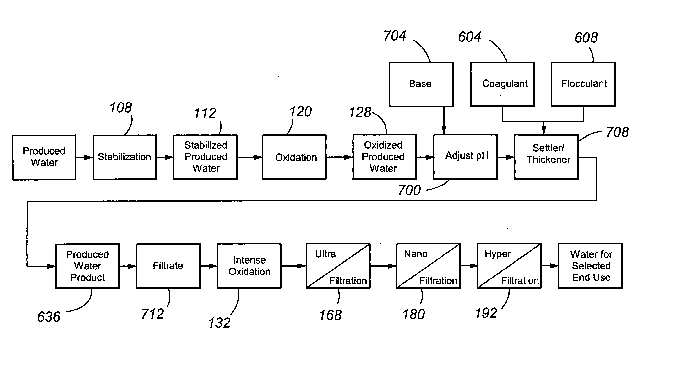
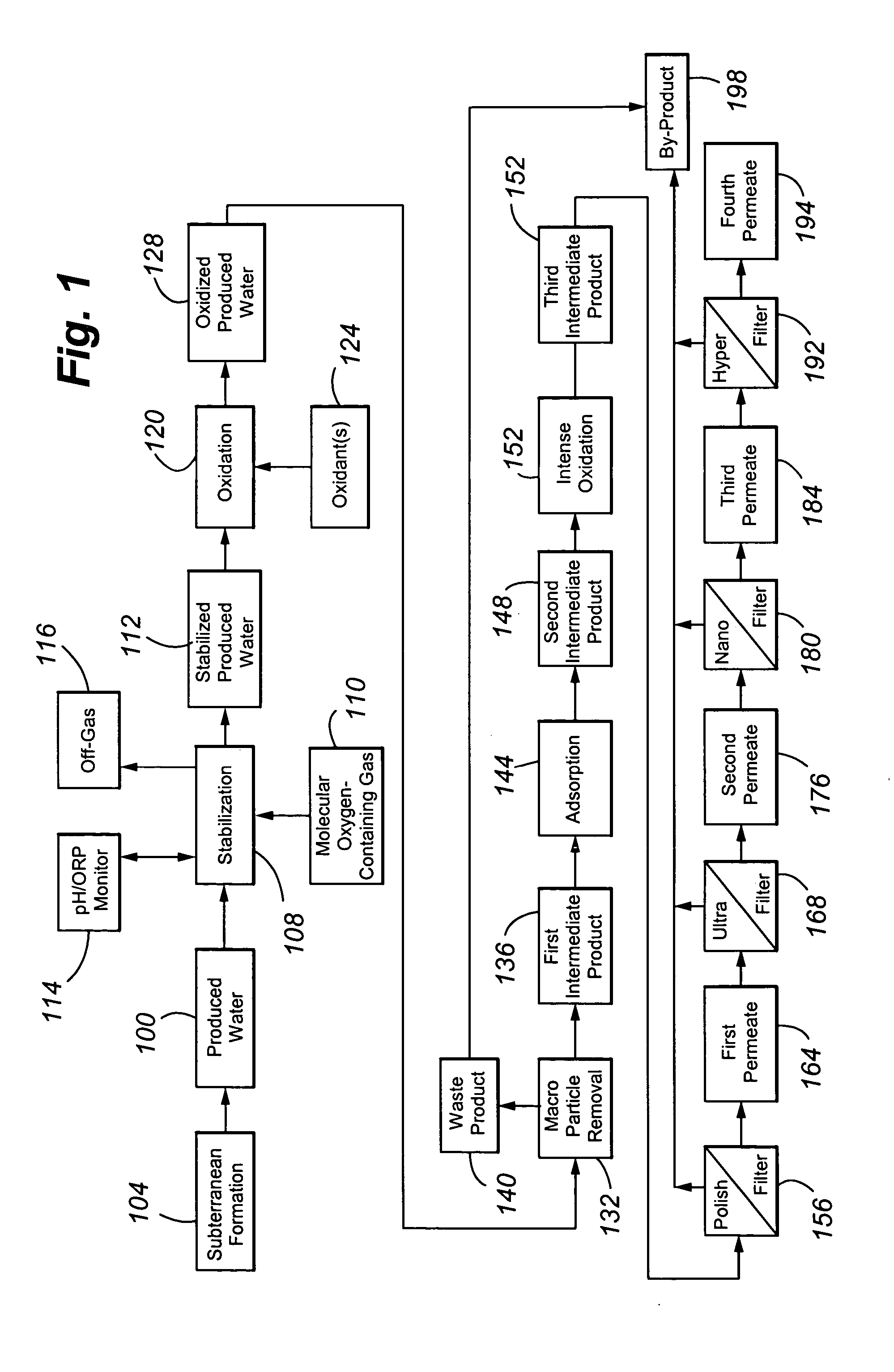
[0056] The process of the present invention is a produced water treatment method in which industrial process feed waters are defined and purified waters generated by a sequence of treatments that, in aggregate, define a “baseline water treatment” train for the removal of contaminants and production of beneficial end use waters. End use waters are generally in compliance with federal clean drinking water standards and are used for a wide variety of uses including revegetation of well sites, fire protection, drilling and workover operations, process cooling, road maintenance, stream bed makeup and groundwater aquifer recharge, landscape irrigation of golf courses, city parks and the like, livestock watering, wildlife habitats, and crop irrigation. All or parts of the treatment train can be used on an as-required and optional basis to achieve defined water quality standards. The process of the present invention can integrate the evolving social demand for conservation of resources with...


PUM

PropertyMeasurementUnit
standard reduction potentialaaaaaaaaaa
diameteraaaaaaaaaa
pHaaaaaaaaaa

Abstract

The present invention is directed to various sets of unit operations for treating aqueous effluents and logic for designing and effecting the treatment. The unit operations include stabilization of subterranean waters, sequential oxidation steps to alter selected target materials, oxidation to break up emulsions prior to removal of the emulsion components, and intense oxidation to break up difficult-to-remove organic target materials.

Description

CROSS REFERENCE TO RELATED APPLICATION [0001] The present application claims the benefits of U.S. Provisional Application Serial No. 60 / 675,775, filed Apr. 27, 2005, entitled “Treatment for SAG-D Oil Field Produced Water and Method of Same”; U.S. Provisional Application Serial No. 60 / 696,000, filed Jul. 1, 2005, entitled “A Treatment for Oil and Gas Field Water, including “Flow-Back Fluid” Contaminated Produced Water, and Method for Operating Same,” and U.S. Provisional Application Serial No. 60 / 774,689, filed Feb. 17, 2006, entitled “Oil and Gas “Produced Water” Treatment and Method for Operating Same,” each of which is incorporated herein by this reference.FIELD OF THE INVENTION [0002] The present invention relates generally to water treatment and specifically to the removal of oil, grease, emulsions, chemicals, polymers, and suspended and dissolved solid contaminants using membranes. BACKGROUND OF THE INVENTION [0003] The production of aqueous and gaseous hydrocarbon commodities ...

Claims


Application Information

Patent Timeline
Patent Type & Authority Applications(United States)
IPC IPC(8): B01D61/00
CPCB01D17/085B01D61/022B01D61/025B01D61/027B01D61/04B01D61/142B01D61/145B01D61/147B01D61/16B01D61/58B01D2311/04B01D2317/025C02F1/001C02F1/20C02F1/24C02F1/283C02F1/32C02F1/40C02F1/42C02F1/44C02F1/441C02F1/444C02F1/5236C02F1/56C02F1/66C02F1/722C02F1/74C02F1/76C02F1/78C02F9/00C02F2101/32C02F2101/322C02F2101/325C02F2103/06C02F2103/365C02F2209/006C02F2209/04C02F2209/06C02F2305/10C02F1/72C02F1/52B01D2311/2649B01D2311/12B01D61/026B01D61/146B01D61/149B01D61/029
Inventor LOMBARDI, JOHN A.TRANQUILLA, JAMESBUTER, LARRY J.HAWTHORNE, WILLIAMBRUNK, KENNETH A.HERBERT, GARY J.GREEN, DENNIS H.
Owner HW PROCESS TECH
Why Eureka
Try Eureka