
Modular Solid-State Laser Platform Based On Coaxial Package And Corresponding Assembly Process

a laser platform and coaxial package technology, applied in the direction of optical resonator shape and construction, optical elements, instruments, etc., can solve the problems of large and cumbersome products, failure to capitalize on the thermal management and ruggedness of fiberized configuration, and no breakthrough in product performance, etc., to achieve the effect of reducing power consumption, reducing size and broadening the operating temperature rang

Inactive Publication Date: 2007-05-24
LUMENTUM OPERATIONS LLC
View PDF19 Cites 13 Cited by
  • Summary
  • Abstract
  • Description
  • Claims
  • Application Information

AI Technical Summary

Benefits of technology

This solution reduces size and power consumption, broadens the operating temperature range, and facilitates high output power with fiber amplifiers, enabling cost-effective mass production and versatile applications, including UV generation and nonlinear frequency conversion.

Problems solved by technology

However, these devices were based on standard microlasers with bulk packaging without fiber coupling, resulting in a large and cumbersome product.
In particular, they do not capitalize on the thermal management and ruggedness of a fiberized configuration.
However, no corresponding packaging or assembly process has been developed, so that no breakthrough was obtained in the product performance.
However operation was limited to a very low repetition rate (<10 Hz).
Moreover, the assembly process relied on manual dynamic alignment with subsequent gluing, and therefore was not suitable for volume production and cost reduction.
The TO-3 package also did not afford output coupling through a fiber.
However, for a given microchip, non-optimized pumping conditions lead to very limited product performance.
While coaxial packages and associated assembly processes have been developed for fiberoptic communication components such as WDM, filters, attenuators, to date no attempt has been made to apply them to solid-state lasers.
The mechanical parts also do not offer the degrees of freedom for adjusting the focus of the pump diode or for adjusting the relative lateral position of the different optical parts.
No provision has been made for coupling into an output fiber, so there is no opportunity to build a versatile product platform on this technology.
The quick-disconnect fiber connector also provides poor positional accuracy, which could be detrimental to the performance of a passively Q-switched microchip laser, where output performance parameters are directly related to the pump intensity.
As a consequence, the disclosed design may not be directly applied to pulsed microchip lasers.
While this arrangement may be satisfactory in C.W. lasers, it is not directly applicable to pulsed microchip lasers.
The cylindrical package disclosed is monolithic, so that it offers no degree of freedom for adjusting the relative position of the optical parts (focusing, resonator).
While the arrangement of optical elements in the cylindrical housing is quasi-monolithic, no degrees of freedom are provided for alignment of the optical parts.
Accordingly, as described previously, the stability and reproducibility of the laser performance will be considerably limited.
As no output fiber coupling is provided, there is little opportunity to build a versatile product platform based on the disclosed technology.
In the case where ultraviolet laser radiation is generated, deposition of organic contamination under UV light may limit the reliability of the laser, because all optical parts are exposed, being located in the same housing.
A lower yield in the process will result due to the higher number of rejected parts, thereby increasing the manufacturing cost.
Such stresses can fracture the laser crystal under strong pumping.
However, no reference is made to the temperature dependence of the laser performance.
Most of these issues are related to the laser packaging.

Method used


Image

  • Modular Solid-State Laser Platform Based On Coaxial Package And Corresponding Assembly Process
  • Modular Solid-State Laser Platform Based On Coaxial Package And Corresponding Assembly Process
  • Modular Solid-State Laser Platform Based On Coaxial Package And Corresponding Assembly Process

Examples


Embodiment Construction

[0047] The present invention relates to the application of coaxial packaging techniques to diode-pumped passively Q-switched microchip lasers.

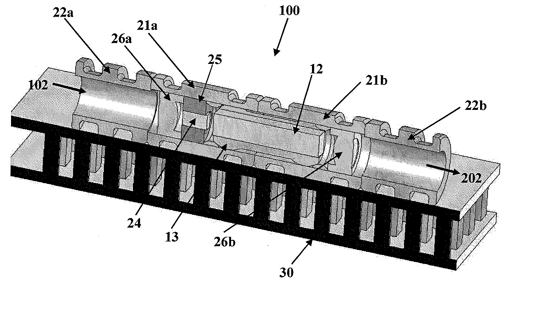
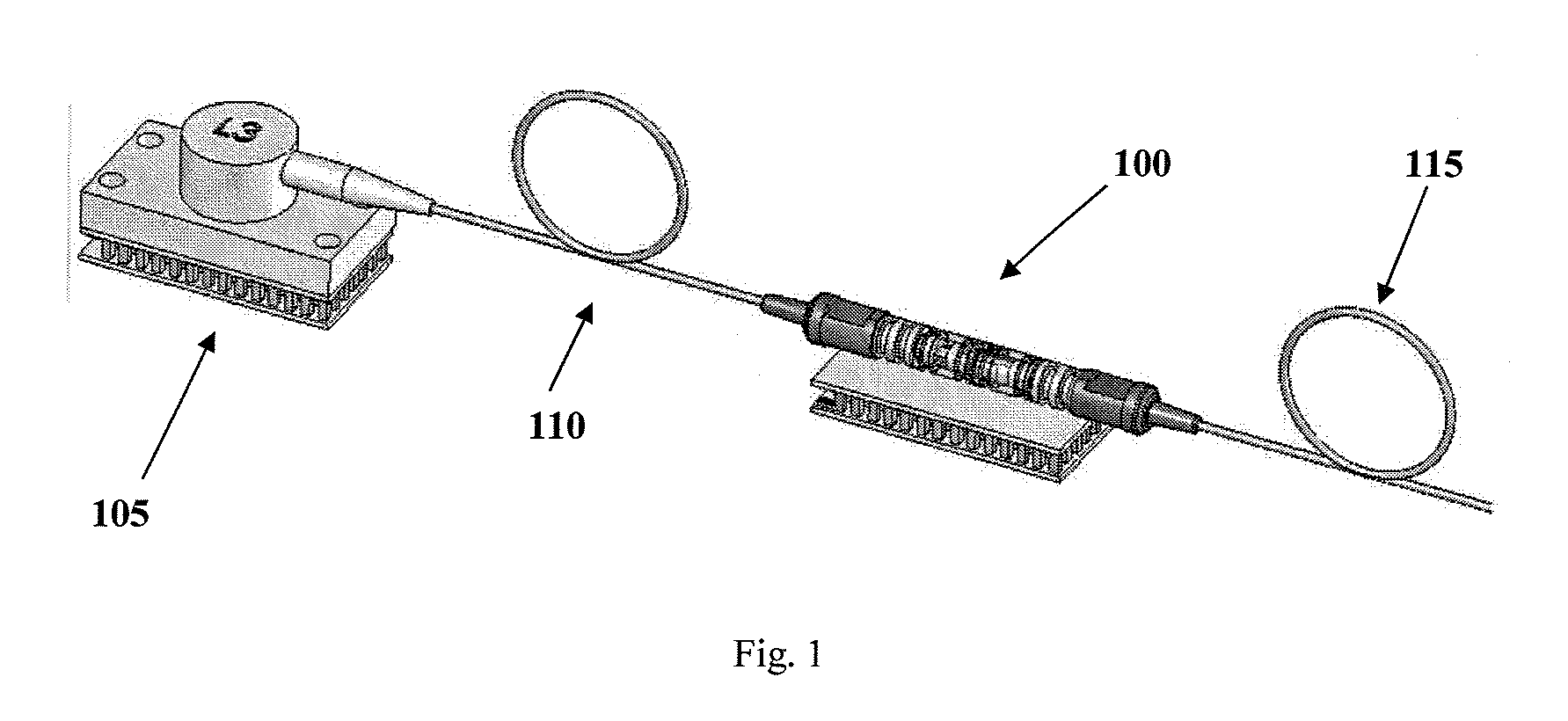
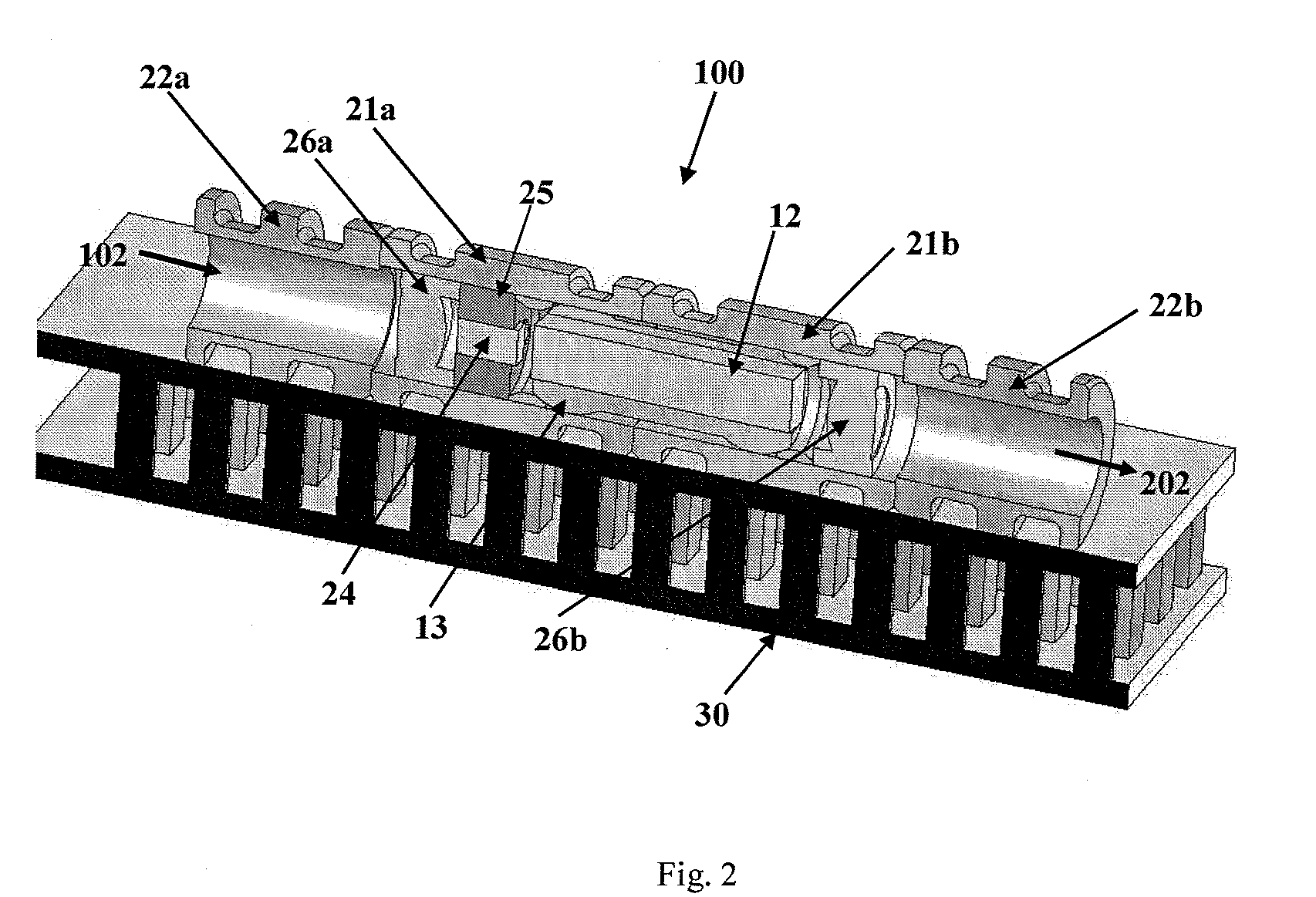
[0048]FIG. 1 shows an exemplary application of the present invention, in which a microlaser mounted within a coaxial package 100, receives pump energy from a fiber-coupled laser diode source 105 (e.g. L3 pump module) through fiber 110. The resulting output from the microlaser 100 is coupled into fiber 115, which is available for further application to an optical amplifier, distributed temperature sensing or generation of supercontinuum, or similar.

[0049] An advantage of the disclosed coaxial packaging 100 is to simplify the use of the fiber-coupled pump diodes 105, leading to a more homogeneous pump beam, which then provides near-optimal pumping of the microlaser 100.

[0050] In addition, the use of a coaxially packaged microlaser 100 in conjunction with standard communication components brings benefits through volume cost reduction. The micr...


PUM


Abstract

Application of a modular coaxial package design, compatible with telecommunication passive component packaging, to microchip lasers, in particular to passively Q-switched microlasers, pumped with a fiber-coupled diode, is disclosed. The number of parts is thereby reduced while providing the adequate degrees of freedom for the active or passive alignment of the optical elements within the package.

Description

CROSS REFERENCE TO RELATED APPLICATIONS [0001] This application claims priority of U.S. Provisional Patent Application No. 60 / 718,780 filed Sep. 20, 2005, entitled “A modular passively q-switched microlaser with controllable peak power density, coaxial package platform and assembly process” which is incorporated herein by reference for all purposesFIELD OF THE INVENTION [0002] The present invention relates to a coaxial packaging platform used in the manufacture of passive optical components, and in particular to an assembly process suitable for large-scale manufacturing of passively Q-switched solid-state lasers. The platform provides for pumping the microlasers through a fiber using a pig-tailed pump source and fiber output coupling. BACKGROUND OF THE INVENTION [0003] Conventional passively Q-switched microlasers were disclosed in U.S. Pat. No. 5,394,413 issued Feb. 28, 1995 to Zayhowski. [0004] The pumping of microlasers by fiber-coupled pump diodes has also been widely disclosed ...

Claims


Application Information

Patent Timeline
Patent Type & Authority Applications(United States)
IPC IPC(8): H01S3/08
CPCH01S3/005H01S3/025H01S3/0405H01S3/042H01S3/0602H01S3/0606H01S3/0612H01S3/0627H01S3/06754H01S3/094053H01S3/094076H01S3/09415H01S3/101H01S3/1022H01S3/1026H01S3/106H01S3/108H01S3/113H01S3/1611H01S3/1643H01S3/2375
Inventor FEVE, JEAN-PHILIPPEHILT, THIERRYLANDRU, NICOLASMAILLARD, MAGALIE
Owner LUMENTUM OPERATIONS LLC
Learn More