Optical information recording method and optical information recording medium

a technology of optical information and recording medium, which is applied in the direction of optical recording/reproducing/erasing methods, optical beam sources, instruments, etc., can solve the problems of insufficient levels of other recording characteristics such as reflectance and modulation, and achieve stable recording and reproducing characteristics, high density, and high recording characteristics.

Inactive Publication Date: 2007-05-31
FUJIFILM CORP
View PDF55 Cites 7 Cited by
  • Summary
  • Abstract
  • Description
  • Claims
  • Application Information

AI Technical Summary

Benefits of technology

[0014] It is an object of the present invention to provide an optical information recording medium that is capable of recording at high density and has high recording characteristics. Another object of the invention is to pro

Problems solved by technology

However, the present inventors have found that practically employable sensitivity cannot be obtained with the discs disclosed in the above publications when information is recorded on the discs by irradiating the discs with short-wave laser beam having a wavelength of 450 nm or less, and that sufficient levels cannot been achieved with respect to other recording characteristics such as reflectance and modul

Method used


Image

  • Optical information recording method and optical information recording medium
  • Optical information recording method and optical information recording medium
  • Optical information recording method and optical information recording medium

Examples


example 1

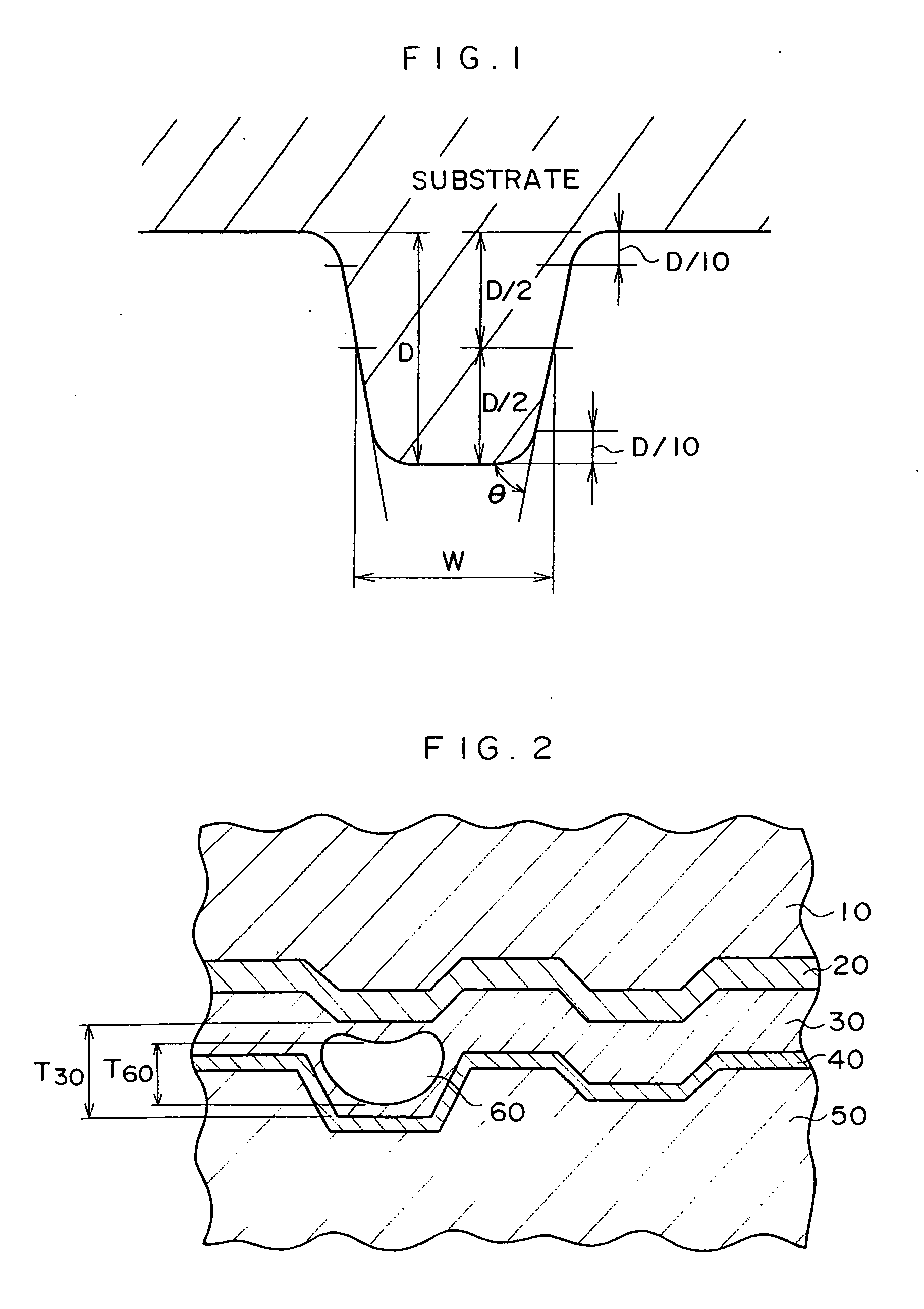
[0141] The grooved side of a polycarbonate resin substrate, which was obtained by injection molding, was DC-sputtered using CUBE (manufactured by Unaxis) in an argon atmosphere to form a light-reflective layer of Ag (thickness: 100 nm). A layer thickness was adjusted by controlling a sputtering time.

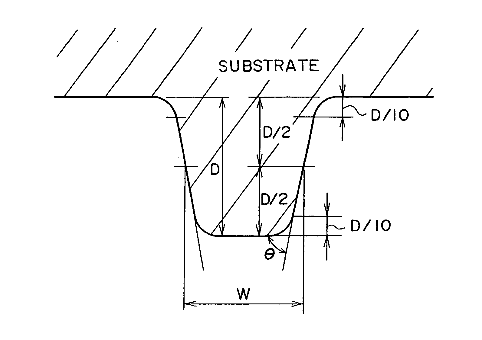
[0142] The resulting substrate had a thickness of 1.1 mm, an outside diameter of 120 mm and an inside diameter of 15 mm, and had a spiral groove (groove depth (a height of the on-groove): 34 nm, width (a width of the on-groove: 105 nm and track pitch: 320 nm)). An inclination angle of the groove as measured by AFM was 57°.

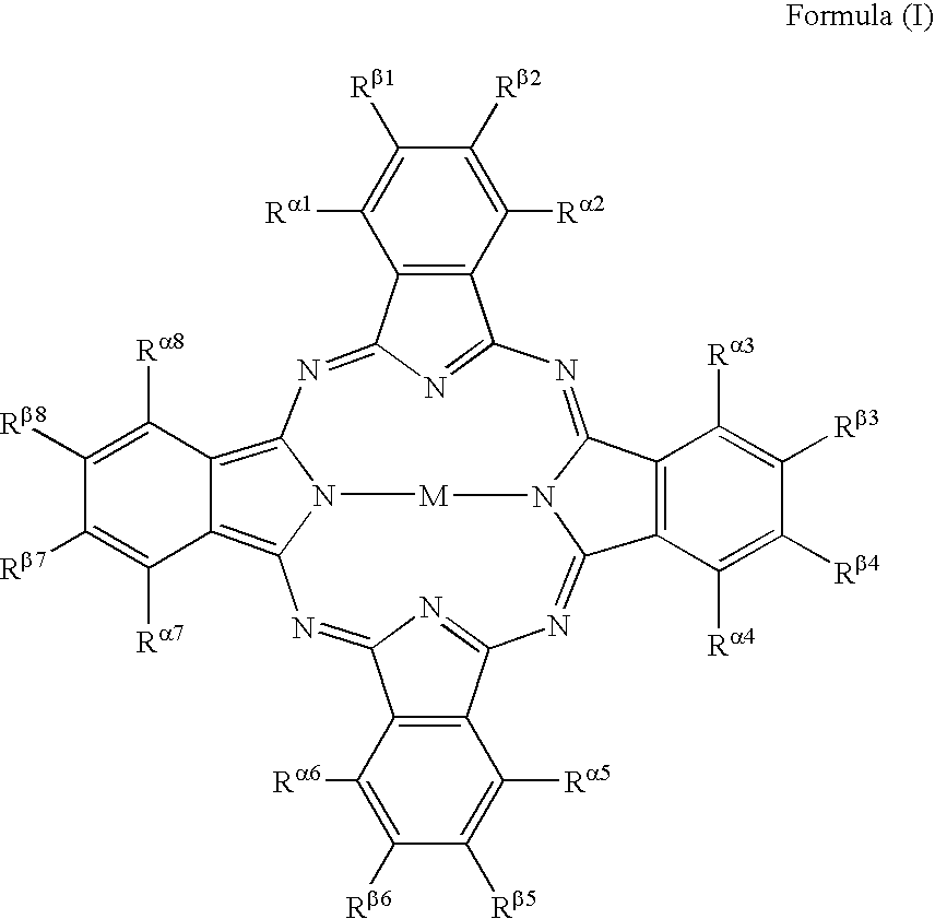
[0143] 2 g of a dye represented by the following chemical formula (wherein Rn represents α-SO2C4H9; and M represents Cu) was dissolved in 100 ml of 2,2,3,3-tetrafluoropropanol to prepare a dye coating solution. The prepared dye coating solution was spin-coated on the light-reflective layer, by varying rotational frequency from 300 to 4,000 rpm under the conditions of ...

example 2

[0151]

[0152] The grooved side of a spirally grooved substrate made of polycarbonate (Panlite AD5503, manufactured by Teijin Limited), which was obtained by injection molding and which had a groove depth of 40 nm, a width of 150 nm and a track pitch of 340 nm and had a thickness of 1.1 mm, an outside diameter of 120 nm and an inside diameter of 15 mm, was DC-sputtered in an argon atmosphere to form a light-reflective layer of AgPdDu alloy (thickness: 120 nm).

[0153] 2.5 g of a dye A (n=1.88, k=0.042) represented by the following chemical formula was dissolved in 100 ml of 2,2,3,3-tetrafluoropropanol to prepare a dye coating solution. The prepared dye coating solution was spin-coated on the light-reflective layer by varying rotational frequency from 300 to 4,000 rpm under the conditions of 23° C. and 50% RH. Thereafter, the substrate was kept at 23° C. and 50% RH for one hour to form a dye recording layer (a thickness of the in-groove portion: 120 nm and a thickness of the on-groove p...

examples 3 and 4

, and Comparative Examples 2 and 3

[0160] Information was recorded on a non-recorded optical information recording medium that was produced using the same optical information recording method as in Example 2, except that the pulse width and power of laser light were changed to those shown in Table 8 to record random signals. Assessment of jitter was carried out in the same manner as in Example 2. The obtained results are summarized in Table 8 above.

[0161] As is apparent from the results summarized in Table 8, it was impossible to measure a jitter of optical information recording media of Comparative Examples 2 and 3. In contrast, optical information recording media of Examples 2 to 4, on which information had been recorded by the optical information recording method of the present invention, had a favorably suppressed jitter, revealing that the optical information recording medium of the present invention has excellent and stable, recording and reproducing characteristics.

[0162] As...


PUM


Abstract

The present invention provides an optical information recording medium including a substrate with an on-groove and an in-groove, having successively disposed thereon a dye recording layer and a transparent sheet, wherein a width of the on-groove ranges from 50 to 140 nm, and a barrier layer is formed between the recording layer and the transparent sheet. The invention also provides an optical information recording method including irradiating the optical information recording medium with laser light from the side of the medium provided with a cover layer to form a void at a signal pit portion in the dye recording layer and thereby carrying out recording of information as well as an optical information recording medium on which information has been recorded by the method.

Description

CROSS-REFERENCE TO RELATED APPLICATION [0001] This application claims priority under 35 USC 119 from Japanese Patent Application Nos. 2002-368061 and 2003-1952, the disclosures of which are incorporated by reference herein. BACKGROUND OF THE INVENTION [0002] 1. Field of the Invention [0003] The present invention relates to an optical information recording method and an optical information recording medium. More specifically, the invention relates to a method of recording on a write-once optical information recording medium by heat mode, and an optical information recording medium on which optical information has been recorded by the recording method. [0004] 2. Description of the Related Art [0005] Write-once optical information recording media on which information can be written only once by irradiating with laser light are called CD-Rs and are widely known. CD-Rs have an advantage in that information is reproducible using a commercially available CD player, and in recent years has ...

Claims


Application Information

Patent Timeline
IPC IPC(8): G11B7/24G11B7/0045G11B7/007G11B7/125G11B7/24079G11B7/244G11B7/246G11B7/2467G11B7/247G11B7/2472G11B7/2478G11B7/248G11B7/249G11B7/2492G11B7/253G11B7/2534G11B7/254G11B7/2542G11B7/256G11B7/257G11B7/258
CPCG11B7/00451G11B7/00452G11B7/1263G11B7/24079G11B7/244G11B7/2467G11B7/258G11B7/2478G11B7/248G11B7/2492G11B7/2534G11B7/2542G11B7/2472G11B7/246G11B7/0045
Inventor USAMI, YOSHIHISAKAKUTA, TAKESHIISHIDA, TOSHIO
Owner FUJIFILM CORP
Why Eureka
Try Eureka