Ceramic-coated medical and biopsy appliances and fabrication method therefore

a technology of ceramic film and biopsy tube, which is applied in the field of ceramic film medical or biopsy tube, can solve the problems of high risk of ceramic film peeling, unfavorable effects, and tissue tear-off, and achieve the intended obj

Inactive Publication Date: 2007-05-31
JFE STEEL CORP
View PDF8 Cites 37 Cited by
  • Summary
  • Abstract
  • Description
  • Claims
  • Application Information

AI Technical Summary

Benefits of technology

[0039] 47. A fabrication system for fabricating a ceramic-coated genetic control needle comprising a magnetron sputtering apparatus, a sample holder and a differential-pressure high-vacuum chamber in a vacuum vessel of a dry plating system, characterized in that a metal needle as a coating object is set on the sample holder as positioned in parallel with an approaching direction of deposition particle...

Problems solved by technology

As to the use of the conventional puncture needle, however, unfavorable effects, such as cellular or tissular destruction and tissue tear-off, on tissue slices collected from the lesion or on tissue areas around the puncture needle at the site of penetration into the lesion have been pointed out, because a substrate of the needle is formed of a conductive metal, such as stainless steel, high tension steel or the like, having good electrical properties (resistance ρ: 10−6-10−8 Ω·m).
However, the ceramic puncture needles and the ceramic needles are very fragile and tend to break easily, and therefore are not currently adopted in any case.
If, however, the ceramic film coated on a very fine cylindrical body like the puncture needle has poor adhesion to a surface of the cylindrical body, the ceramic film will be peeled off during use so that the intended object cannot be achieved.
Particularly, the puncture needles and injection needles are unavoidably flexed to some degree when used, thus involving...

Method used


Image

  • Ceramic-coated medical and biopsy appliances and fabrication method therefore
  • Ceramic-coated medical and biopsy appliances and fabrication method therefore
  • Ceramic-coated medical and biopsy appliances and fabrication method therefore

Examples


example 1

[0175] A ferritic stainless steel material, containing C: 0.039 mass %, Si: 0.25 mass %, Mn: 0.12 mass %, P: 0.008 mass %, S: 0.012 mass %, and Cr: 18.9 mass % with the remainder being Fe and unavoidable impurities, was subjected to continuous casting process, followed by hot rolling, cold rolling and bright annealing, and then high-precision worked into biopsy forceps, forceps, surgical scissors and a surgical knife.

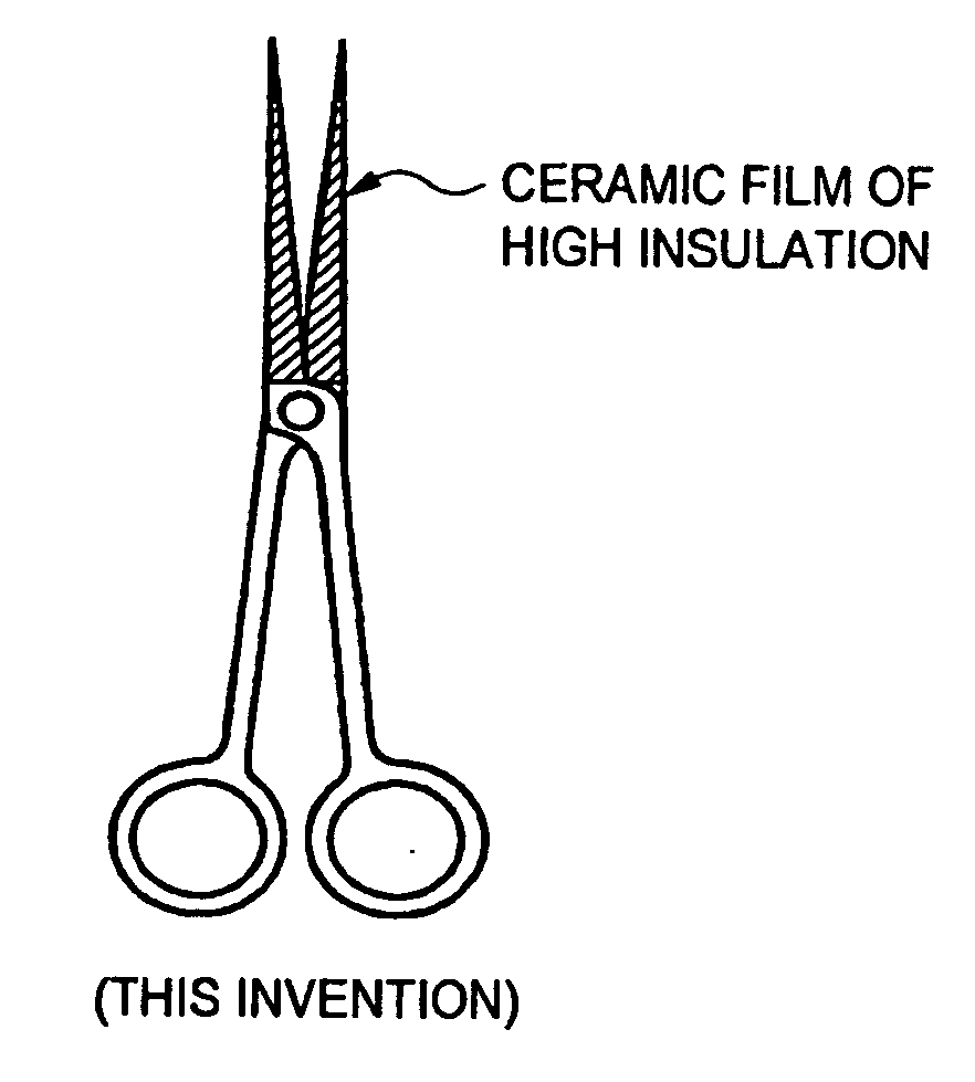
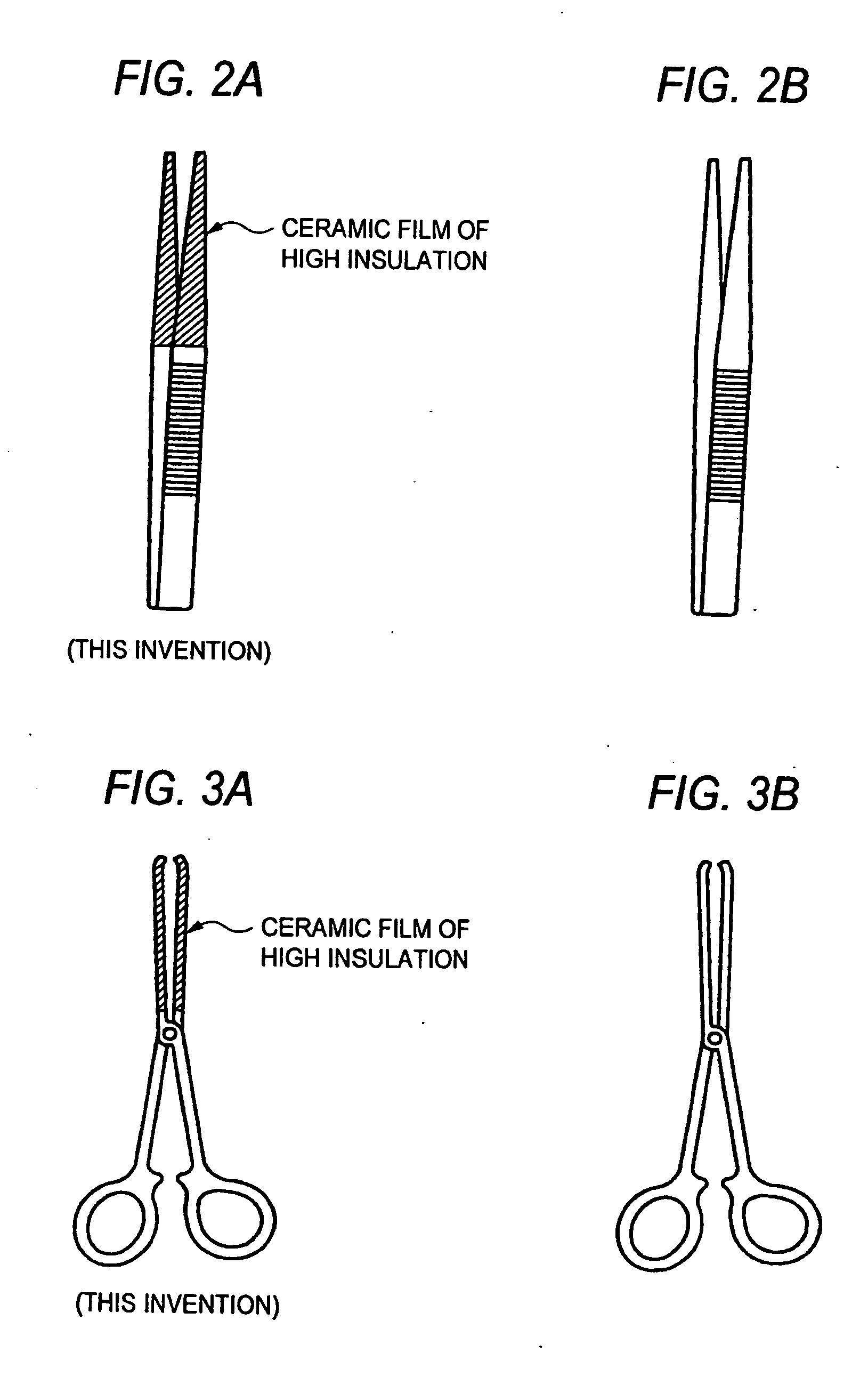
[0176] Subsequently, the medical appliances were supersonically cleaned and subjected to the magnetron sputtering process illustrated in FIG. 5 for formation of various ceramic films on the individual portions shown in FIGS. 2A to 4A. Specifically, the SiNx film was formed on the biopsy forceps, the SiO2 film was formed on the forceps, a BN film was formed on the surgical scissors, and an Al2O3 film was formed on the surgical knife. For comparison purpose, a TiN film was formed on the biopsy forceps. All the coating films had a thickness of about 1 μm. Thickness measur...

example 2

[0180] A ferritic stainless steel material, containing in mass percentage C: 0.033%, Si: 0.20%, Mn: 0.15%, P: 0.008%, S: 0.008%, and Cr: 17.7% with the remainder being Fe and unavoidable impurities, was subjected to continuous casting process, followed by hot rolling, cold rolling and bright annealing, and then high-precision worked into a puncture needle (outside diameter: 2.0 mm, length: 170 mm), biopsy forceps, forceps, surgical scissors and a surgical knife.

[0181] Subsequently, the medical appliances were supersonically cleaned and subjected to the magnetron sputtering process illustrated in FIG. 5 (with the RF device also used in some step) for formation of various ceramic films listed in Table 2 in the high-plasma atmosphere. In the coating process, the former stage was carried out in the normal coating atmosphere, whereas the latter stage (surface coating portion: 0.5 μm in thickness) was carried out with oxygen gas introduced in the atmosphere in different amounts. All the ...

example 3

[0185] A ferritic stainless steel material (a) containing C: 0.03 mass %, Si: 0.2 mass %, Mn: 0.15 mass %, P: 0.010 mass %, S: 0.010 mass %, and Cr: 18.8 mass % with the remainder being Fe and unavoidable impurities; and an austenite stainless steel material (b) containing C: 0.05 mass %, Si: 0.3 mass %, Mn: 0.20 mass %, P:0.012 mass %, S: 0.011 mass %, Cr: 19.1 mass %, Ni: 9.1 mass % and Mo: 0.25 mass % with the remainder being Fe and unavoidable impurities were each subjected to continuous casting process, followed by hot rolling, cold rolling and bright annealing, and then high-precision worked into a contrast medium needle having an outside diameter of 0.8 mm and a length of 200 mm. After supersonically cleaned, the contrast medium needles were set in the magnetron sputtering system shown in FIG. 5 for SiNx film formation in the high plasma atmosphere.

[0186] The magnetron sputtering process formed the SiNx ceramic film in a thickness of 0.8 μm under the conditions of Ar: 100 sc...


PUM


Abstract

Providing a ceramic-coated medical appliance quite excellent in insulating performance which has no negative effects on tissues or cells of an organism subjected to surgery; a ceramic-coated genetic control needle which has no risk of breaking during use nor no unfavorable effects, such as destruction or tear-off, on sliced tissues or tissue areas around the needle at site of penetration into a lesion and which cuts off a cell nucleus or injects an immunological solution into the nucleus without causing any negative effects on tissues around the penetrated needle; and a fabrication method for the same.
Specifically, in the ceramic-coated medial needle, genetic control needle, biopsy forceps and medical appliances such as forceps, surgical scissors and surgical knife, an insulating ceramic film having a resistance ρ of 105 Ω·m or more is formed, by dry plating, at least on a portion, a part or the whole of an outer and/or an inner surface of a metal needle that directly contact an organism, or cells or cell nuclei thereof.

Description

TECHNICAL FIELD [0001] The present invention relates to a ceramic-coated medical or biopsy appliance formed of metal and a fabrication method therefor. Particularly, the invention relates to medical appliances and biopsy appliances which are coated with ceramic coatings on metallic parts thereof that directly contact any part of an organism, and to a fabrication method for the same. The medical and biopsy appliances principally include medical needles such as injection needles, puncture needles for hepatobiopsy / renal biopsy, suture needles and the like; biopsy forceps; forceps; surgical scissors; surgical knives and the like. The invention further relates to a ceramic-coated genetic control needle and a fabrication method therefor. BACKGROUND ART [0002] The recent medical technologies have made a dramatic leap forward. In liver and pancreas examinations, for example, a variety of examination methods are commonly used for acquiring data not available from blood test. Such examination...

Claims


Application Information

Patent Timeline
IPC IPC(8): A61B17/32A61B17/00A61B10/00A61B10/02A61B10/06A61B17/06A61B17/122A61B17/30
CPCA61B10/02A61B10/06A61B17/06A61B17/06066A61B17/122A61B17/30A61B17/3201A61B17/3211A61B2017/0084A61B2017/0088
Inventor INOKUTI, YUKIOMORI, HIROTAROFUKUDA, HIROYUKIEBARA, MASAAKI
Owner JFE STEEL CORP
Why Eureka
Try Eureka