Stage drive method and stage unit, exposure apparatus, and device manufacturing method

a technology of stage drive and exposure apparatus, which is applied in the direction of photomechanical equipment, instruments, printing, etc., can solve the problems of affecting the quality of the exposure operation, the depth of focus may become so small, and the focus margin shortage may occur during the exposure operation, so as to prevent or improve the throughput, and suppress the leakage of liquid

Inactive Publication Date: 2007-06-07
NIKON CORP
View PDF99 Cites 287 Cited by
  • Summary
  • Abstract
  • Description
  • Claims
  • Application Information

AI Technical Summary

Benefits of technology

[0027] According to this apparatus, when a transition is performed from the first state where one stage is positioned at the first area directly below the projection optical system to which the liquid is supplied to the second state where the other stage is positioned at the first area, the stage drive system simultaneously drives the first stage and the second stage in the second axis direction (the direction intersecting the first axis direction in which the first area and the second area are arranged) while one of a state where the first stage and the second stage are close together in the second axis direction and a state where the first stage and the second stage are in contact in the second axis direction is maintained. This allows the transition from the first state to the second state, in a state where the liquid is held in the space between the projection optical system and at least one stage directly below the projection optical system, while preventing or suppressing the leakage of the liquid from the gap between the first stage and the second stage. That is, during the period after the exposure operation of the substrate on one stage side via the projection optical system and the liquid has been performed until the exposure operation of the substrate on the other stage side via the projection optical system and the liquid begins, it becomes possible to perform the transition from a state where the liquid is held in the space between one stage and the projection optical system to a state where the liquid is held in the space between both of the stages and the projection optical system and then to a state where the liquid is held in the space between the other stage and the projection optical system, without going through the process of fully recovering the liquid and supplying the liquid again. Accordingly, the exposure operation of the substrate on the other stage, which is performed after the exposure operation of the substrate on the one stage has been completed, can be started within a short period, which allows the throughput to be improved. Further, because the liquid constantly exists on the image plane side of the projection optical system, generation of water stains (water marks) on the optical members on the image plane side of the projection optical system can be effectively prevented.
[0028] According to an eighth aspect of the present invention, there is provided a fourth exposure apparatus that supplies a liquid to a space between a projection optical system and a substrate and exposes the substrate via the

Problems solved by technology

However, due to the shorter wavelength of the exposure light and the larger numerical aperture of the projection optical system described above, the depth of focus is becoming narrower.
Further, the exposure wavelength is presumed to be much shorter in the future; however, in such a case, the depth of focus may become so small that focus margin shortage may occur during the exposure operation.
However, when the recovery and the supply of the liquid is performed each time the wafer is exchanged, it is certain that the time required for the recovery and supply of the liquid will cause a decrease in throughput of the exposure apparatus.
This water stain generation may lead to a decreas

Method used


Image

  • Stage drive method and stage unit, exposure apparatus, and device manufacturing method
  • Stage drive method and stage unit, exposure apparatus, and device manufacturing method
  • Stage drive method and stage unit, exposure apparatus, and device manufacturing method

Examples


first embodiment

A First Embodiment

[0068] A first embodiment of the present invention will be described below, referring to FIGS. 1 to 10.

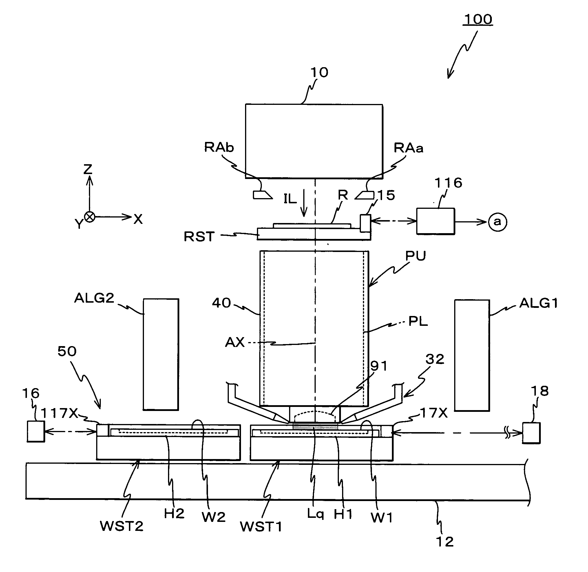
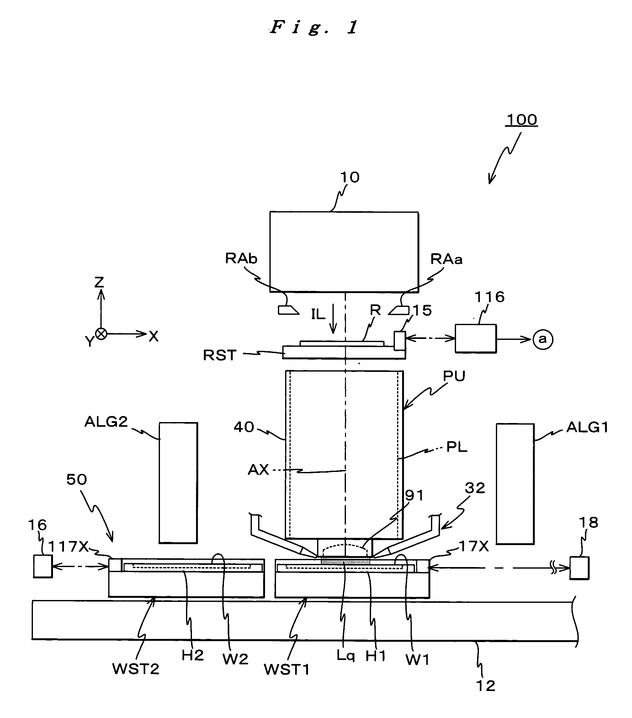
[0069]FIG. 1 schematically shows the entire configuration of an exposure apparatus 100 related to the first embodiment. Exposure apparatus 100 is a projection exposure apparatus by the step-and-scan method, that is, the so-called scanning stepper (also called a scanner). Exposure apparatus 100 is equipped with illumination system 10, a reticle stage RST that holds a reticle R serving as a mask, a projection unit PU, a wafer stage unit 50 that has wafer stages WST1 and WST2, off-axis alignment systems ALGL1 and ALG2, serving as a first and a second mark detection system, a control system for these components or assemblies, and the like. On wafer stages WST1 and WST2, substrates serving as wafers are to be mounted. In FIG. 1, a wafer W1 is mounted on wafer stage WST1, and a wafer W2 is mounted on wafer stage WST2.

[0070] As is disclosed in, for example, Kokai (Japa...

second embodiment

A Second Embodiment

[0173] Next, a second embodiment of the present invention will be described, referring to FIGS. 11 to 15B. For parts that have the same or similar arrangement as the first embodiment previously described, the same reference numerals will be used, and the description thereabout will be brief, or entirely omitted. In the exposure apparatus of the second embodiment, the configuration or the like of the wafer stage unit and the parallel processing operation using the two wafer stages differ from the first embodiment previously described. Further, the point where only one mark detection system is arranged is also different from the first embodiment previously described. The configuration or the like of other components or assemblies are similar to the first embodiment previously described. Accordingly, from the viewpoint of avoiding repetition in the following description, the differences will mainly be described.

[0174]FIG. 11 shows an arrangement of a control system ...

third embodiment

A Third Embodiment

[0230] Next, a third embodiment of the present invention will be described, referring to FIGS. 16 to 18B. For components or assemblies that have the same or similar arrangement as the first embodiment previously described, the same reference numerals will be used, and the description thereabout will be brief, or entirely omitted. In the exposure apparatus of the third embodiment, only the configuration or the like of the wafer stage unit differ from the first embodiment previously described, and the configuration or the like of other components are similar to the first embodiment previously described. Accordingly, from the viewpoint of avoiding repetition in the following description, the differences will mainly be described.

[0231] Different from wafer stage unit 50 that constitutes the exposure apparatus of the first embodiment previously described, as is shown in FIG. 16, a wafer stage unit 50″ of the third embodiment is equipped with a wafer stage WST on which ...


PUM

PropertyMeasurementUnit
Sizeaaaaaaaaaa
Areaaaaaaaaaaa
Energyaaaaaaaaaa

Abstract

When a transition from a first state where one stage is positioned at a first area directly below projection optical system to which liquid is supplied to a state where the other stage is positioned at the first area, both stages are simultaneously driven while a state where both stages are close together in the X-axis direction is maintained. Therefore, it becomes possible to make a transition from the first state to the second state in a state where liquid is supplied in the space between the projection optical system and the specific stage directly under the projection optical system. Accordingly, the time from the completion of exposure operation on one stage side until the exposure operation begins on the other stage side can be reduced, which allows processing with high throughput. Further, because the liquid can constantly exist on the image plane side of the projection optical system, generation of water marks on optical members of the projection optical system on the image plane side is prevented.

Description

TECHNICAL FIELD [0001] The present invention relates to stage drive methods and stage units, exposure apparatus, and device manufacturing methods, and more particularly to a stage drive method in which two stages movable in an area including a first area within a two-dimensional plane where a liquid is locally supplied are driven and a stage unit suitable for implementing the stage drive method, an exposure apparatus that supplies liquid in a space between a projection optical system and a substrate and exposes the substrate via the projection optical system and the liquid, and a device manufacturing method that uses the exposure apparatus. BACKGROUND ART [0002] Conventionally, in a lithography process for manufacturing electronic devices such as a semiconductor device (such as an integrated circuit), a liquid crystal display device or the like, a reduction projection exposure apparatus by the step-and-repeat method that transfers an image of a pattern of a mask or a reticle (herein...

Claims


Application Information

Patent Timeline
IPC IPC(8): G03B27/58G03F7/20
CPCG03F7/70341Y10T29/49155G03F7/70733G03F7/70725G03F7/2006H01L21/0275H01L21/0274G03F7/2041G03F7/70833G03F7/70258G03F7/70758G03F1/44G03F7/70666
Inventor SHIBAZAKI, YUICHI
Owner NIKON CORP
Why Eureka
Try Eureka