Direct conversion energy discriminating ct detector with over-ranging correction

a detector and energy discrimination technology, applied in the field of radiographic detectors for diagnostic imaging, can solve the problems of inability to provide data or feedback as to the number and/or energy of photons detected, ct imaging would not be a viable diagnostic imaging tool, and inability to provide energy discriminatory data or otherwise count the number and/or energy of photons actually received by a given detector element or pixel

Active Publication Date: 2007-06-21
GE GLOBAL RES CENT
View PDF26 Cites 4 Cited by
  • Summary
  • Abstract
  • Description
  • Claims
  • Application Information

AI Technical Summary

Benefits of technology

[0023] The CT detector supports not only x-ray photon counting, but energy measurement or tagging as well. As a result, the present invention supports the acquisition of both anatomical detail as well as tissue characterization information. In this regard, the energy discriminatory information or data may be used to reduce the effects of beam hardening and the like. Further, these detectors support the acquisition of tissue discriminatory data and therefore provide diagnostic information that is indicative of disease or other pathologies. For example, detection of calcium in a plaque in a view is possible. This detector can also be used to detect, measure, and characterize materials that may be injected into a subject such as contrast agents and other specialized materials such as targeting agents. Contrast materials can, for example, include iodine that is injected into the blood stream for better visualization.

Problems solved by technology

A drawback of such detectors however is their inability to provide data or feedback as to the number and / or energy of photons detected.
While it is generally recognized that CT imaging would not be a viable diagnostic imaging tool without the advancements achieved with conventional CT detector design, a drawback of these detectors is their inability to provide energy discriminatory data or otherwise count the number and / or measure the energy of photons actually received by a given detector element or pixel.
Under the charge integration operation mode, the photodiode is not capable of discriminating between the energy level or the photon count from the scintillation.
Such detectors have large detector elements and as such are not readily adapted to CT applications requiring high resolution imaging to capture anatomical detail in the imaged object.
A drawback of direct conversion semiconductor detectors, however, is that these types of detectors cannot count at the x-ray photon flux rates typically encountered with conventional CT systems, e.g. at or above 1 million counts per sec per millimeter squared (1.0 Mcps).
The very high x-ray photon flux rate, above 1.0 Mcps, causes pile-up and polarization which ultimately leads to detector saturation.
Above these thresholds, the detector response is not predictable or has degraded dose utilization.
For SPECT and PET, imaging flux levels are below 1.0 Mcps and such saturation in a semiconductor detector for SPECT and PET is not a practical concern.
What can be problematic, however, is that the bowtie filter may not be optimal given that a subject population is significantly less than uniform and not exactly elliptical in shape.
Low x-ray flux in the projection will ultimately contribute to noise in the reconstructed image of the subject.
Detector saturation causes loss of imaging information and results in artifacts in x-ray projection and CT images.
In addition, hysteresis and other non-linear effects occur at flux levels near detector saturation as well as flux levels over detector saturation.
Direct conversion detectors are susceptible to a phenomenon called “polarization” where charge trapping inside the material changes the internal electric field, alters the detector count and energy response in an unpredictable way, and results in hysteresis where response is altered by previous exposure history.
Incomplete collection of x-rays results in reduced image quality, i.e. a noisy image, and poor utilization of dose to the imaged object.
However, there is a reliability issue to routing of high voltage signals.
This again results in poor dose utilization and image artifacts.
However, small pixel size results in higher cost and there are more channels per unit area which need to be connected to readout electronics.
This sharing of charge results in incomplete energy information and / or a miscount of x-ray photons because the readout electronics are not configured to combine simultaneous signals in neighboring pixels.
Very high flux rates are possible with thin, photon counting, direct conversion silicon layers with pixel size <0.1 mm, but there is not sufficient stopping power in these thin layers to stop the x-rays.
In the case of photodiode, the electronic gain is not sufficient to overcome the electronic noise.
In the case of APDs, there is additional gain but with associated gain-instability noise, temperature sensitivity and reliability issues.
In the case of photomultiplier tubes, these devices are too large and costly for high resolution detectors covering large areas.
Detector saturation can affect image quality by constraining the number of photons used to reconstruct the image and introducing image artifacts.
For CT imaging, the reconstruction is not tolerant to missing or corrupted data.
The reconstruction of the data set with these uncorrected saturated values will cause severe artifacts in the image.
However, this solution leads to increased scanned time.
That is, there is a penalty that the acquisition time for the image is increased in proportion to the nominal flux needed to acquire a certain number of x-rays that meet image quality requirements.

Method used


Image

  • Direct conversion energy discriminating ct detector with over-ranging correction
  • Direct conversion energy discriminating ct detector with over-ranging correction
  • Direct conversion energy discriminating ct detector with over-ranging correction

Examples


Embodiment Construction

[0051] The operating environment of the present invention is described with respect to a four-slice computed tomography (CT) system. However, it will be appreciated by those skilled in the art that the present invention is equally applicable for use with single-slice or other multi-slice configurations. Moreover, the present invention will be described with respect to the detection and conversion of x-rays. However, one skilled in the art will further appreciate that the present invention is equally applicable for the detection and conversion of other radiographic energy.

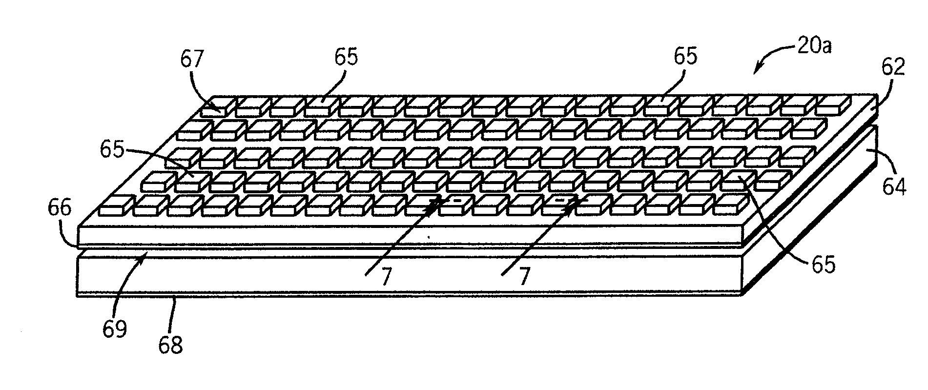
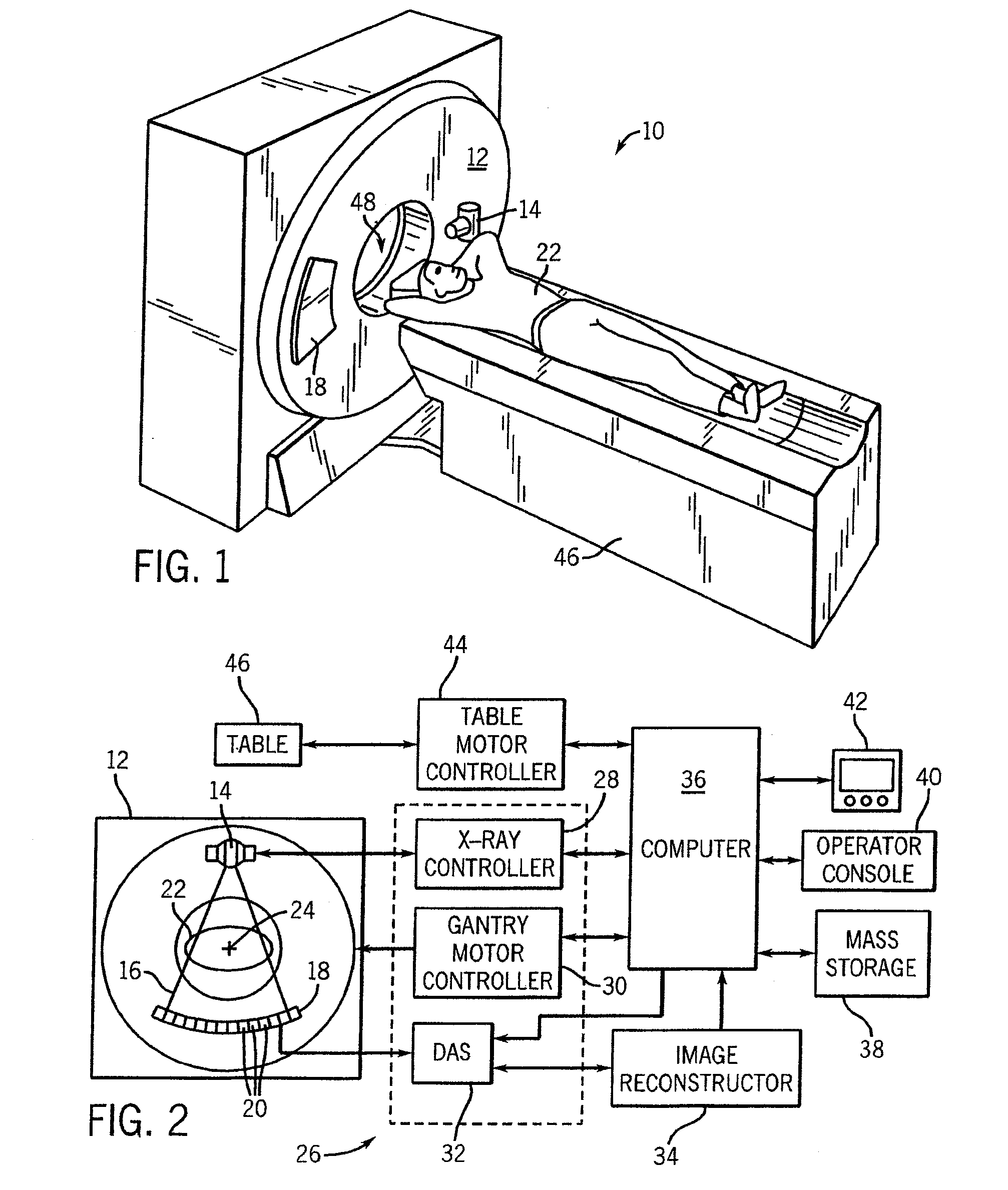
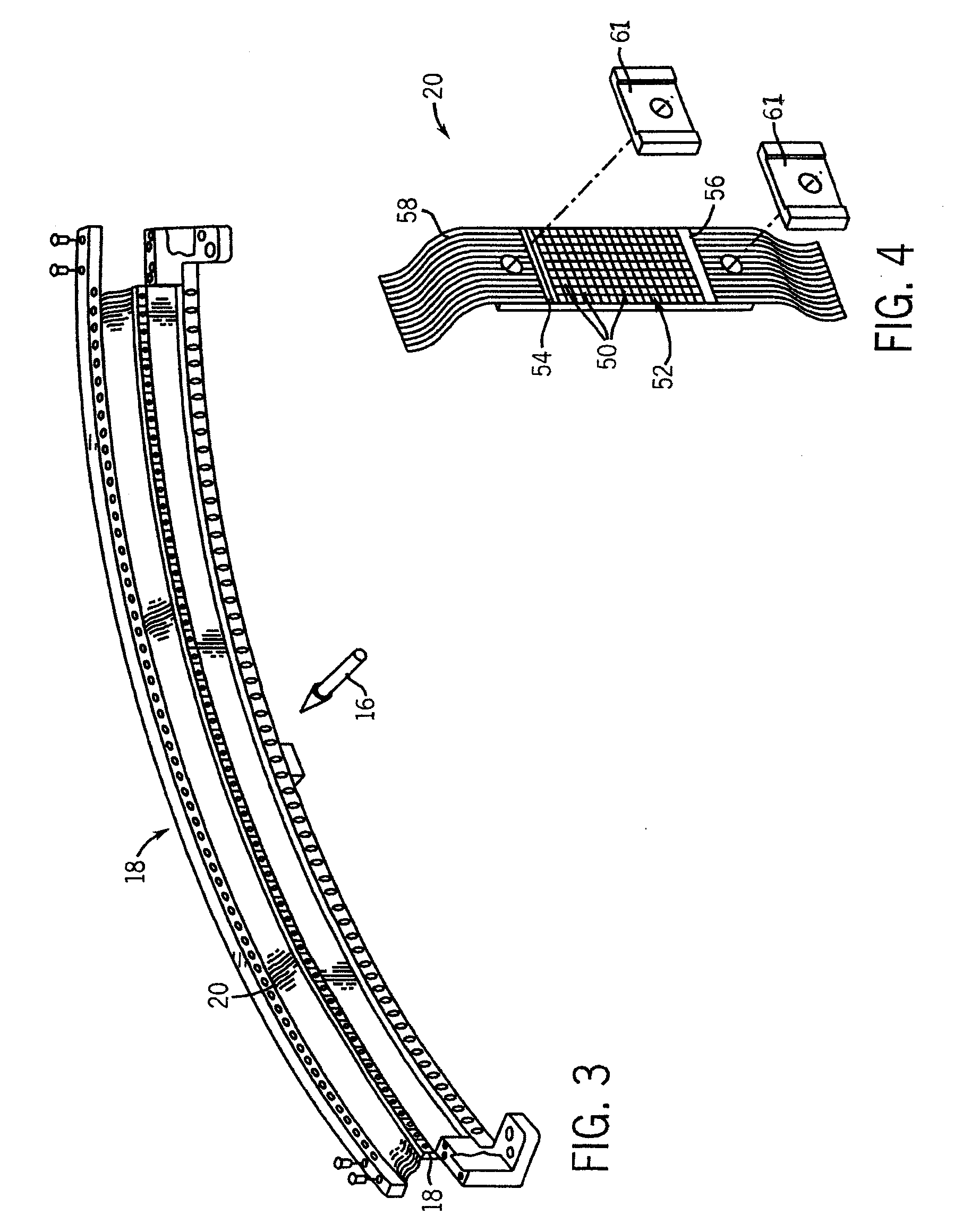
[0052] Referring to FIGS. 1 and 2, a computed tomography (CT) imaging system 10 is shown as including a gantry 12 representative of a “third generation” CT scanner. Gantry 12 has an x-ray source 14 that projects a beam of x-rays 16 toward a detector assembly 18 on the opposite side of the gantry 12. Detector assembly 18 is formed by a plurality of detectors 20 which together sense the projected x-rays that pass thr...


PUM

PropertyMeasurementUnit
total thicknessaaaaaaaaaa
thicknessesaaaaaaaaaa
thickaaaaaaaaaa

Abstract

A CT detector capable of energy discrimination and direct conversion is disclosed. The detector includes multiple layers of semiconductor material with the layers having varying thicknesses. The detector is constructed to be segmented in the x-ray penetration direction so as to optimize count rate performance as well as avoid saturation. The detector also includes variable pixel pitch and a flexible binning of pixels to further enhance count rate performance.

Description

CROSS-REFERENCE TO RELATED APPLICATION [0001] The present application is a continuation of and claims priority of U.S. patent application Ser. No. 10 / 939,787 filed Sep. 13, 2004, the disclosure of which is incorporated herein.BACKGROUND OF THE INVENTION [0002] The present invention relates generally to radiographic detectors for diagnostic imaging and, more particularly, to a multi-layer direct conversion CT detector capable of providing photon count and / or energy data with improved saturation characteristics and over-ranging self-correctability. [0003] Typically, in radiographic imaging systems, such as x-ray and computed tomography (CT), an x-ray source emits x-rays toward a subject or object, such as a patient or a piece of luggage. Hereinafter, the terms “subject” and “object” may be interchangeably used to describe anything capable of being imaged. The beam, after being attenuated by the subject, impinges upon an array of radiation detectors. The intensity of the attenuated bea...

Claims


Application Information

Patent Timeline
Patent Type & Authority Applications(United States)
IPC IPC(8): H05G1/60A61B6/00G01N23/00G21K1/12
CPCA61B6/032A61B6/4241A61B6/5205G01T1/2928
Inventor HOFFMAN, DAVID M.LEBLANC, JAMESTKACZYK, JOHNSENZIG, ROBERT F.DU, YANFENG
Owner GE GLOBAL RES CENT
Why Eureka
Try Eureka