Heat exchanger and method for manufacturing the same

a heat exchanger and heat exchanger technology, applied in the field of aluminum heat exchangers, can solve the problems of affecting the performance affecting the quality of the heat exchanger, so as to prevent the generation of fin detachment, good corrosion resistance, and good corrosion resistance

Inactive Publication Date: 2007-07-19
SHOWA DENKO KK
View PDF11 Cites 5 Cited by
  • Summary
  • Abstract
  • Description
  • Claims
  • Application Information

AI Technical Summary

Benefits of technology

[0037] As mentioned above, according to the present invention, it is possible to provide an aluminum heat exchanger and the manufacturing method thereof capable of maintaining good corrosion resistance for a long period of time and preventing generation of fin detachment, pit corrosion, etc., assuredly.
[0038] The above and / or other aspects, features and / or advantages of various embodiments will be further appreciated in view of the following description in conjunction with the accompanying figures. Various embodiments can include and / or exclude different aspects, features and / or advantages where applicable. In addition, various embodiments can combine one or more aspect or feature of other embodiments where applicable. The descriptions of aspects, features and / or advantages of particular embodiments should not be construed as limiting other embodiments or the claims.

Problems solved by technology

As disclosed in the aforementioned Patent Document 1, in the technique for thermally spraying Zn on the surface of a heat exchanger tube, if the Zn adhering amount is increased at the time of thermally spraying Zn on the surface of the heat exchanging tube, excessive Zn will be diffused in the brazing portion (i.e., fillet), causing preferential corrosion of the fillet.
However, since the Zn thermal spraying for spraying a low amount of Zn becomes unstable, adhesion amount becomes uneven, resulting in unstable sacrificial corrosion layer throughout the entire sprayed area.
As a result, partial corrosion occurs when used for a long time period, causing pit corrosion.
Furthermore, as shown in the aforementioned Patent Documents 2 and 3, in the technology which forms a corrosion resistant coat by chemical conversion treatment on a heat exchanger surface, although a uniform corrosion resistant coat can be formed broadly, the corrosion resistance could not be maintained for a long period of time, and therefore generation of pit corrosion, etc., can not be prevented effectively.

Method used


Image

  • Heat exchanger and method for manufacturing the same
  • Heat exchanger and method for manufacturing the same
  • Heat exchanger and method for manufacturing the same

Examples


example 1

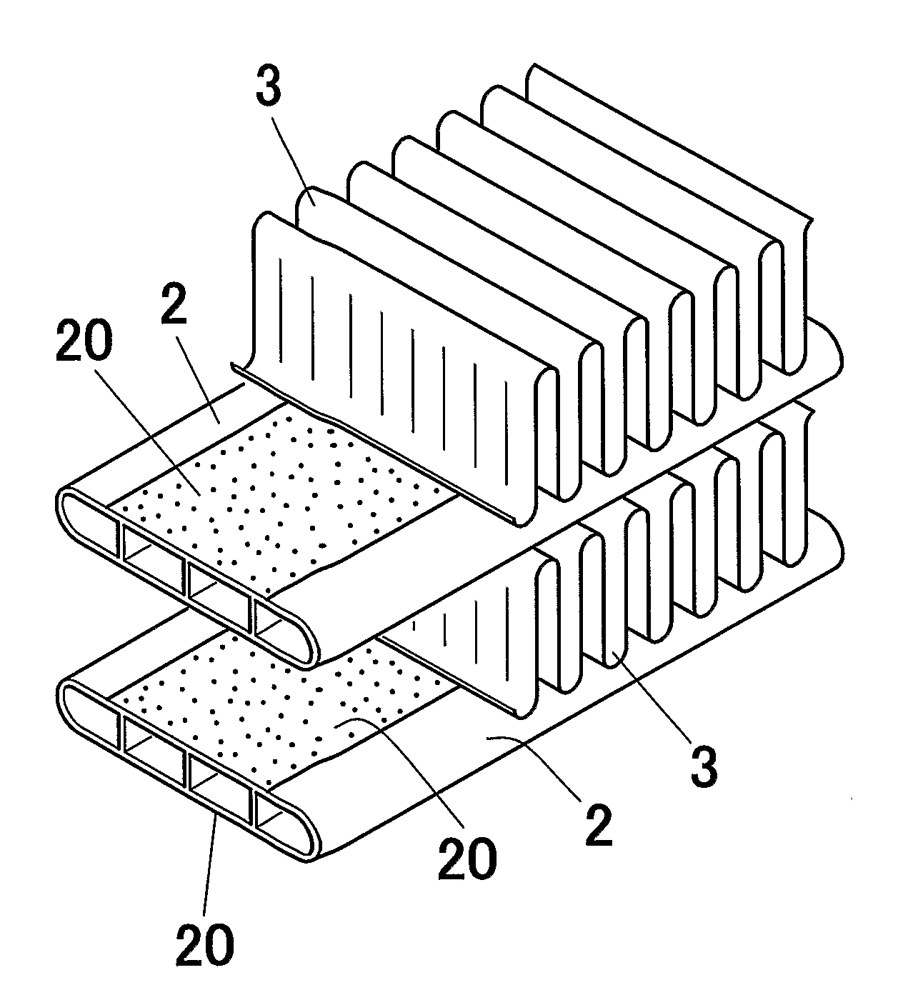
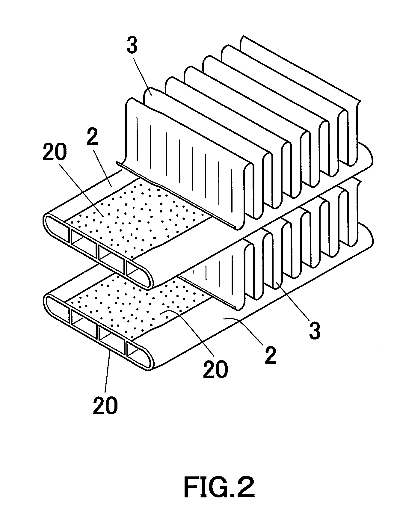
[0066] Using extruded material consisting of Al alloy (Cu: 0.4 mass %, Mn: 0.15 mass %, balance being Al), a multi-bored flat tube having a width of 16 mm, a height of 3 mm and a thickness of 0.5 mm was extruded with an extrusion machine. On the other hand, thermal spraying guns of an arc thermal spraying machine were disposed at upper and lower sides of the outlet of the extrusion machine to thermally spraying Zn onto the upper and lower sides of the extruded tube to thereby form thermally sprayed layers. Thereafter, the tube with thermally sprayed layers (tube (heat exchanger tube) was cooled in a cooling bath and rolled into a coil shape.

[0067] As shown in the following Table 1, in the aforementioned thermal spraying processing, the Zn adhesion amount was adjusted to 1 g / m2.

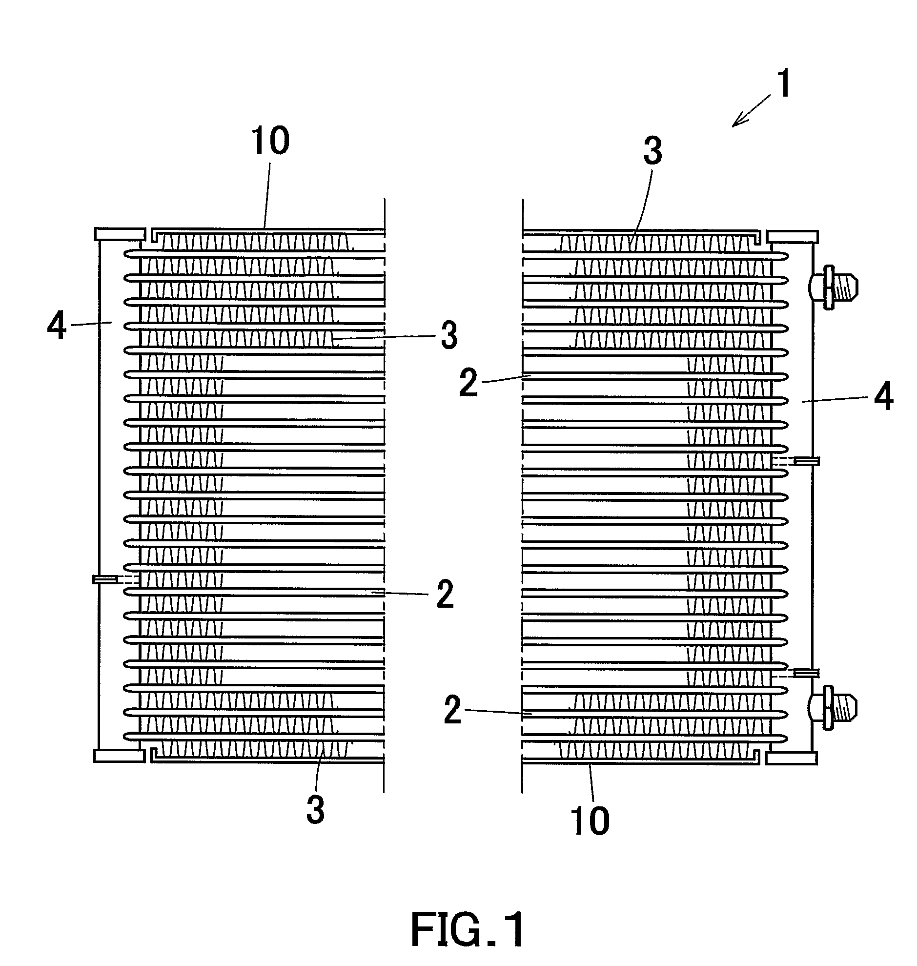
[0068] Using the aforementioned heat exchanger tubes, a provisionally assembled heat exchanger having the same structure as that of the aforementioned multi-flow type heat exchanger (see FIG. 1) as explained...

examples 2 to 6

[0071] As shown in Table 1, heat exchanger samples were prepared by the same processing as mentioned above, except that the Zn adhesion amount were adjusted to 2, 4, 6, 8, 10 g / m2 during the thermal spraying processing.

examples 7 to 9

[0072] Samples were prepared by the same processing as mentioned above, except that the Zn adhesion amount were adjusted to 3, 4, 7 g / m2 as shown in Table 1 during the thermal spraying processing and that fluoridation titanium series chemical conversion treatment agent was used as chemical conversion treatment agent. The chemical conversion treatment was performed using chemical conversion treatment agent in which 100 ppm concentration of zirconium ion was contained in water medium under the conditions that the aforementioned heat exchanger core was immersed for 90 seconds in a bath that the aforementioned chemical conversion treatment agent was heated to 50° C.


PUM

PropertyMeasurementUnit
thicknessaaaaaaaaaa
heightaaaaaaaaaa
widthaaaaaaaaaa

Abstract

A method for manufacturing an aluminum heat exchanger includes the steps of: obtaining a heat exchanger tube 2 by forming a Zn thermally sprayed layer on a surface of an aluminum flat tube core so as to adjust Zn adhesion amount to 1 to 10 g/m2; obtaining a heat exchanger core by alternatively arranging the heat exchanger tube 2 and an aluminum fin 3 and brazing the heat exchanger tube and the fin with end portions of the heat exchanger tube connected to aluminum headers in fluid communication; and forming a chemical conversion treatment coat (corrosion resistance coat) on a surface of the heat exchanger core by subjecting the surface of the heat exchanger core to chemical conversion treatment using at least one chemical conversion treatment agent selected from the group consisting of phosphoric acid chromate, chromic acid chromate, phosphoric acid zirconium series, phosphoric acid titanium series, fluoridation zirconium series, and fluoridation titanium series. The obtained heat exchanger has a long last good corrosion resistance and can prevent occurrence of fin detachment and pit corrosion.

Description

[0001] This application claims priority under 35 U.S.C. §119 to Japanese Patent Application No. 2004-35356 filed on Feb. 12, 2004 and U.S. Provisional Application No. 60 / 545,529 filed on Feb. 19, 2004, the entire disclosures of which are incorporated herein by reference in their entireties. CROSS REFERENCE TO RELATED APPLICATIONS [0002] This application is an application filed under 35 U.S.C. §111(a) claiming the benefit pursuant to 35 U.S.C. §119(e)(1) of the filing date of U.S. Provisional Application No. 60 / 545,529 filed on Feb. 19, 2004, pursuant to 35 U.S.C. §111(b).TECHNICAL FIELD [0003] The present invention relates to an aluminum heat exchanger for use in, for example, a car air-conditioning refrigerant cycle and a method for manufacturing the same. [0004] In this disclosure, the wording of “aluminum” is used to include the meaning of aluminum and its alloy. BACKGROUND ART [0005] The following description sets forth the inventor's knowledge of related art and problems therei...

Claims


Application Information

Patent Timeline
Patent Type & Authority Applications(United States)
IPC IPC(8): F28F13/18C23C22/34C23C22/36F25B39/04F28D1/053F28F19/06F28F21/08
CPCC23C22/34C23C22/361F25B39/04F28F21/084F28D2021/0084F28F19/06F28D1/05366
Inventor MINAMI, KAZUHIKOTANAKA, DAISHINAKAGAWA, SHINTARO
Owner SHOWA DENKO KK
Why Eureka
Try Eureka