Panoramic image-based virtual reality/telepresence audio-visual system and method

a technology of audio-visual system and panoramic image, applied in the field of panoramic image-based virtual reality/telepresence audio-visual system and method, can solve the problems of low resolution image scene, limitation compounded further, and the conventional camcorder is not tailored to recording panoramic image, so as to facilitate wireless transmission and facilitate incorporation. easy and cost-effective

Inactive Publication Date: 2007-08-09
RITCHEY KURTIS J
View PDF4 Cites 224 Cited by
  • Summary
  • Abstract
  • Description
  • Claims
  • Application Information

AI Technical Summary

Benefits of technology

[0003] An advantage of using a single conventional camcorder to record panoramic images is that it is readily available, adaptable, and affordable to the average consumer. However, the disadvantage is that conventional camcorders are not tailored to recording panoramic images. For instance, a limitation of the claim 4 lens is that transmitting image segments representing all portions of a spherical FOV scene to a single frame results in a scene of low resolution image when a portion of that scene is enlarged. This limitation is compounded further when overlapping images are recorded adjacent to one another on a single frame in order facilitate stereographic recording. For example, the Canon XL1 camcorder with inter-changeable lens capability produces an EIA standard television signal of 525 lines, 60 fields, NTSC color signal. The JVC JY-HD10U HDTV Camcorder produces a 1280×720P image in a 16:9 format at 60 fields, color signal. And finally the professional Sony HDW-F900 produces a 1920×1080 image in a 16:9 format at various frame rates to include 25, 29.97, and 59.94 fields per second color signal. The images can be recorded in either a progressive or interlaced mode. Assuming two fisheye lenses are used to record a complete scene of spherical coverage, it is preferable that each hemispherical image be recorded at a resolution of 1000×1000 pixels. While HDTV camcorders represent an improvement they still fall short of this desired resolution. The optical systems put forth in the present invention facilitates recording images nearer to or greater than the 1000×1000 pixel resolution desired, depending on which of the above cameras is incorporated. It is therefore an objective of the present invention to provide several related methods for adapting and enhancing a single conventional camcorder to record a higher resolution spherical FOV images.
[0032] Additionally, technologies enabling and incorporated into the present invention 120 or 122 include wireless technology that has done away with the requirements for physical connections from the viewers camera, head-mounted display, and remote control of the camera to host computers required for image processing and control processing. Wireless connectivity of can be realized in the panoramic capable wireless communication terminals / units 120, 122 by the use of conventional RF and Infrared transceivers. Corresponding, recent hardware and software / firmware such as Intel™ Centrino™ mobile technology, Bluetooth technology, and Intel's™ Bulverde™ chip processor allows easy and cost-effective incorporation of video camera capabilities into wireless laptops, PDA's, smart cellular phones, HMDs, and so forth that enable wireless devices to conduct panoramic video-teleconferencing and gaming using the panoramic capable wireless communication terminals / units 120, 122 according to the present invention. These technologies may be part of the components and systems incorporated into the present invention. For example, these wireless technologies are enabling and incorporated into the present invention in order to realize the wireless image based remote control unit that is wrist mounted is claimed in the present invention to control spherical FOV cameras and head mounted displays. Chips and circuitry which include transceivers allow video and data signals to be sent wirelessly between the input, processing and display means units 120 when distributed over the users body or off the users body. Specifically, for example, the Intel Pro / Wireless 2100 LAN MiniPCI Adapters Types 3A and 3B provide IEEE 802.11b standard technology. The 2100 PCB facilitates the wireless transmission of up to eleven megabits per second and can be incorporated into embodiments of the Panoramic capable wireless communication terminals / units 120 or 122 of the present invention.

Problems solved by technology

However, the disadvantage is that conventional camcorders are not tailored to recording panoramic images.
For instance, a limitation of the claim 4 lens is that transmitting image segments representing all portions of a spherical FOV scene to a single frame results in a scene of low resolution image when a portion of that scene is enlarged.
This limitation is compounded further when overlapping images are recorded adjacent to one another on a single frame in order facilitate stereographic recording.
While HDTV camcorders represent an improvement they still fall short of this desired resolution.
A limitation of the current panoramic optical assemblies that incorporate wide angle and fisheye lenses is that the recorded image is barrel distorted.
The problem with this is that it takes time and computer resources.
A limitation current panoramic camcorders is that they rely on magnetic tape media.
Another limitation is that the microphone(s) on the above conventional camcorders is not designed for panoramic recording.
This does not work well with a panoramic camera system using the optical assembly in claim 4 records a spherical FOV because the microphone gets in the way of visually recording the surrounding panoramic scene.
Another limitation is that the tripod socket mount on the above conventional camcorders is not designed to facilitate panoramic recording.
Conventional camcorder mounting sockets are typically on the bottom of the camera and do not facilitate orienting the camera lens upward toward the ceiling or sky.
A limitation of current cameras is that no tripod socket is on the rear of the camera, opposite the lens end of the camera.
Another limitation of current camcorders is that they have not been designed to facilitate recording panoramic imagery and conventional directional zoom lens imagery without changing lenses.
Another limitation is that the control mechanism on the above conventional camcorders is not designed for panoramic recording.
This does not work well with the panoramic camera system using the optical assembly in claim 4 records a spherical FOV such that the camera operator cannot hide when manually operating the controls of the camera.
Another limitation is that the viewfinder on the above conventional camcorders is not designed for panoramic recording.
This does not work well with the panoramic camera system using the optical assembly in claim 4 records a spherical FOV such that the camera operator cannot hide when manually operating the controls of the camera.
Another limitation is that the remote control receiver(s) on the above conventional camcorders is not designed for camcorders adapted for panoramic recording.
When the camcorder is placed upward the remote control signal does not readily communicate with the remote control device because the receivers are facing upward to the sky and downward toward the ground.
A previous limitation of panoramic camcorder systems is that image segments comprising the panoramic scene required post production prior to viewing.
A previous limitation of the camcorder system has been that there is no way to designate what subjects in a recorded panoramic scene to focus in on.
There has also not been a method to extract from the panoramic scene a sequence of conventional imagery of a limited FOV of just the designated subjects.
A previous limitation of panoramic camcorder systems is that panoramic manipulation and viewing software was not incorporated / embedded into the panoramic camcorder system and / or panoramic remote control unit.
A current limitation of humans is that while we live in a three-dimensional environment, our senses have limitations in perceiving our three-dimensional environment.
One of these constraints is that our sense of vision only perceives things in one general direction at any one time.
Similarly, typical camera systems are designed to only facilitate recording, processing, and display of a multi-media event within a limited field-of-view.
However, Strub et al. does not disclose the idea of incorporating a spherical field-of-view camera system.
Strub et al. does not disclose a system that looks back at the wearers face.
The above Ritchey prototype and IPIX / Coastal systems have not incorporate recent micro-optics which have reduced the required size of the optic.

Method used


Image

  • Panoramic image-based virtual reality/telepresence audio-visual system and method
  • Panoramic image-based virtual reality/telepresence audio-visual system and method
  • Panoramic image-based virtual reality/telepresence audio-visual system and method

Examples


second embodiment

[0202] the present invention will be described with reference to FIG. x. In an IL-CCD, it is possible to obtain video information of field accumulation without mixing the signal charges from two adjacent photoelectric converting elements as is done in the case of the foregoing embodiment. The principle is described referring to FIGS. x and x. FIG. x shows the pulse (VBLK) representing the vertical blanking period, the field pulse emitted from the synchronizing signal generator 4 shown in FIG. x, the signal readout timing of the IL-CCD, the driving timing of the liquid crystal shutters, the potential change in the photoelectric converting element at point Z, and the output signal from the imaging device.

[0203] The following describes the operation. During the first field, the signal readout pulse .phi.CH is applied to .phi.V3 to transfer the signal charges generated at the photoelectric converting element 42 to the vertical transfer stage. The signal charges are then transferred at h...

first embodiment

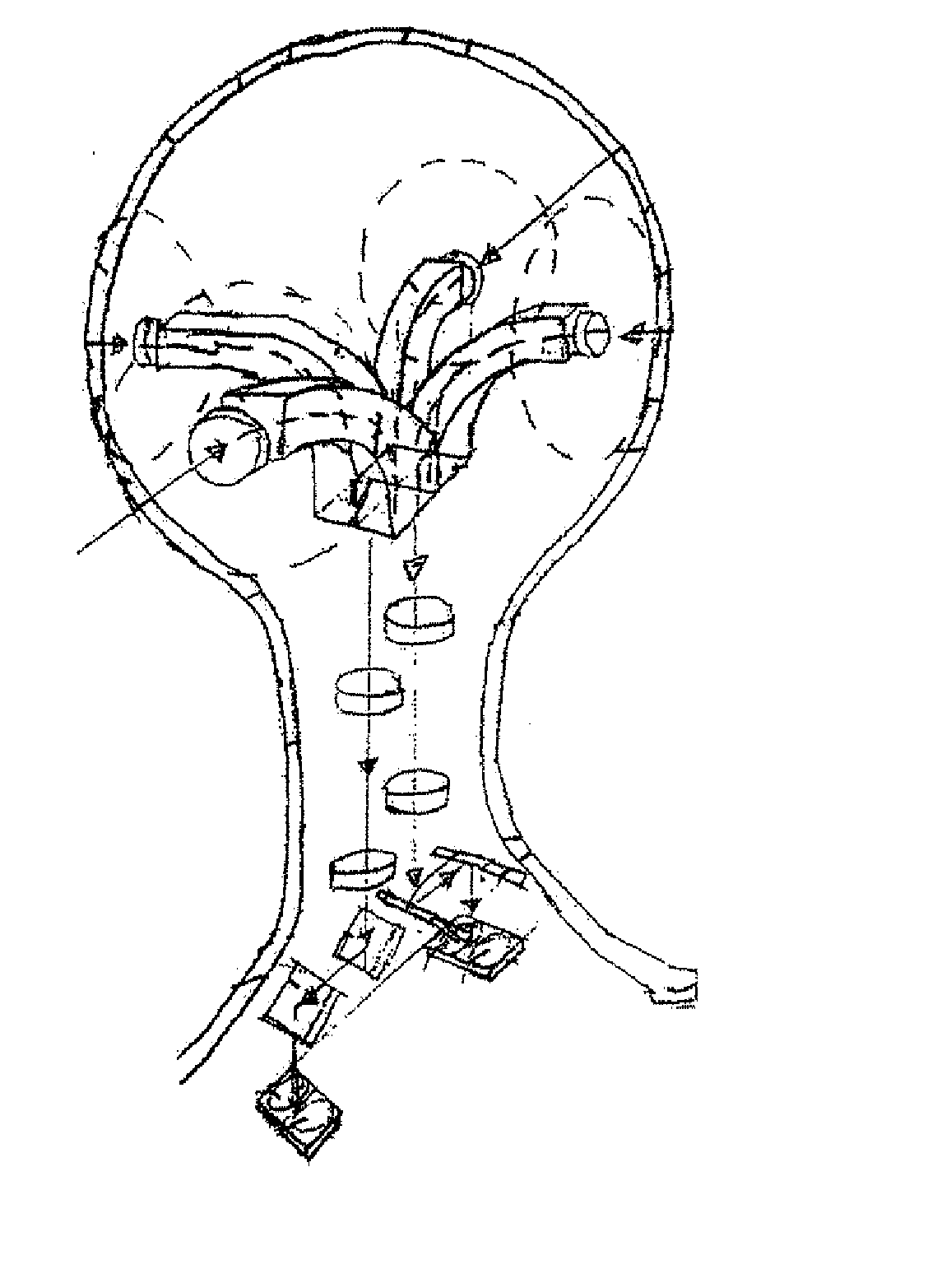
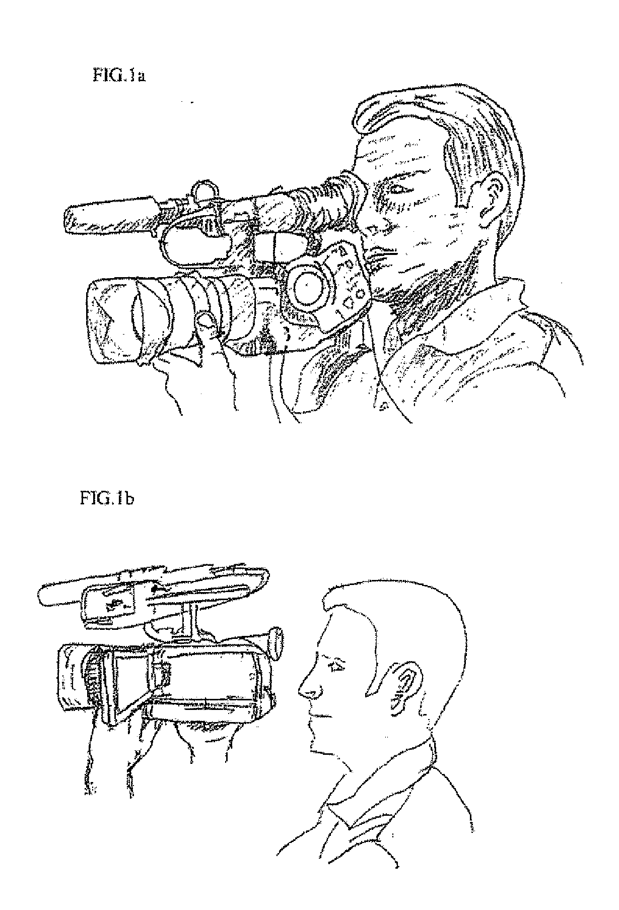
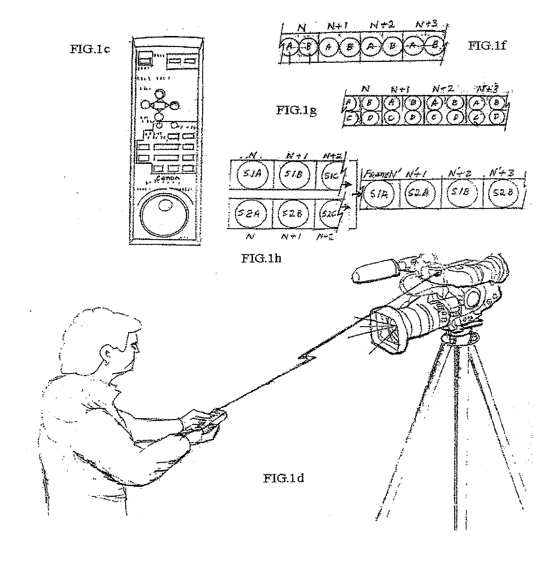
[0306] For example, and now referring to the drawings in more detail, FIG. 19 and FIG. 37 is a perspective drawing of a personal communication system 120 or 122 comprising a head-mounted wireless panoramic communication system according to the present invention. This first embodiment of the personal communication system includes a camera system comprising objective lenses, relay optics, focusing lenses, shutters, and imaging sensor means. FIG. 36a through FIG. 36i is a schematic diagram comprising nine drawings that can be placed next to one another to describe all major embodiments of the present invention and will be referenced throughout the detailed description. A legend of how the images fit together can be found on the bottom left corner of FIG. 36a.

[0307] Referring to embodiment A of FIG. 19 and FIG. 37, shown in FIG. 20, FIG. 21, FIG. 27, and FIG. 36a, the objective lenses and associated objective relay or focusing lenses transmit images representing the environment surroun...


PUM


Abstract

A panoramic system comprises means for obtaining a panoramic image, and means for displaying the panoramic image.

Description

CROSS-REFERENCE TO RELATED APPLICATIONS [0001] The present application claims the benefit of U.S. Provisional Patent Application Ser. No. 60 / 572,408, filed May 19, 2004, which is incorporated herein by reference in its entirety.BACKGROUND AND SUMMARY OF THE INVENTION [0002] In U.S. Pat. No. 5,130,794, claim 5, the present inventor disclosed a portable system incorporating a plurality of cameras for recording a spherical FOV scene. In that same patent, claim 4, the present inventor disclosed an optical assembly that can be constructed and placed on a conventional camcorder that enables the camcorder to record spherical field-of-view (FOV) panoramic images. Similarly, in U.S. Pat. No. ______, IPIX later claims a portable plural camera system for recording panoramic imagery. However, in many instances using a single camcorder is advantageous because most people cannot afford to buy several camcorders, one camcorder for recording panoramic spherical FOV imagery and one for recording con...

Claims


Application Information

Patent Timeline
Patent Type & Authority Applications(United States)
IPC IPC(8): H04N7/00
CPCH04N5/2254H04N21/4305H04N5/23238H04N5/2259H04N23/55H04N23/58H04N23/60H04N23/698
Inventor RITCHEY, KURTIS J.
Owner RITCHEY KURTIS J
Why Eureka
Try Eureka