
Patterning Method For Biosensor Applications And Devices Comprising Such Patterns

a biosensor and pattern technology, applied in the field of patterning a biosensor layer, can solve the problems of inability to accommodate biological molecules or water soluble polymers, high equipment requirements, time-consuming, etc., and achieve the effect of not being attractive to biosensors, pedot/pss, and aggressive chemicals or polymers unreactive to biosensors

Inactive Publication Date: 2007-08-23
BIOCHROMIX
View PDF5 Cites 22 Cited by
  • Summary
  • Abstract
  • Description
  • Claims
  • Application Information

AI Technical Summary

Benefits of technology

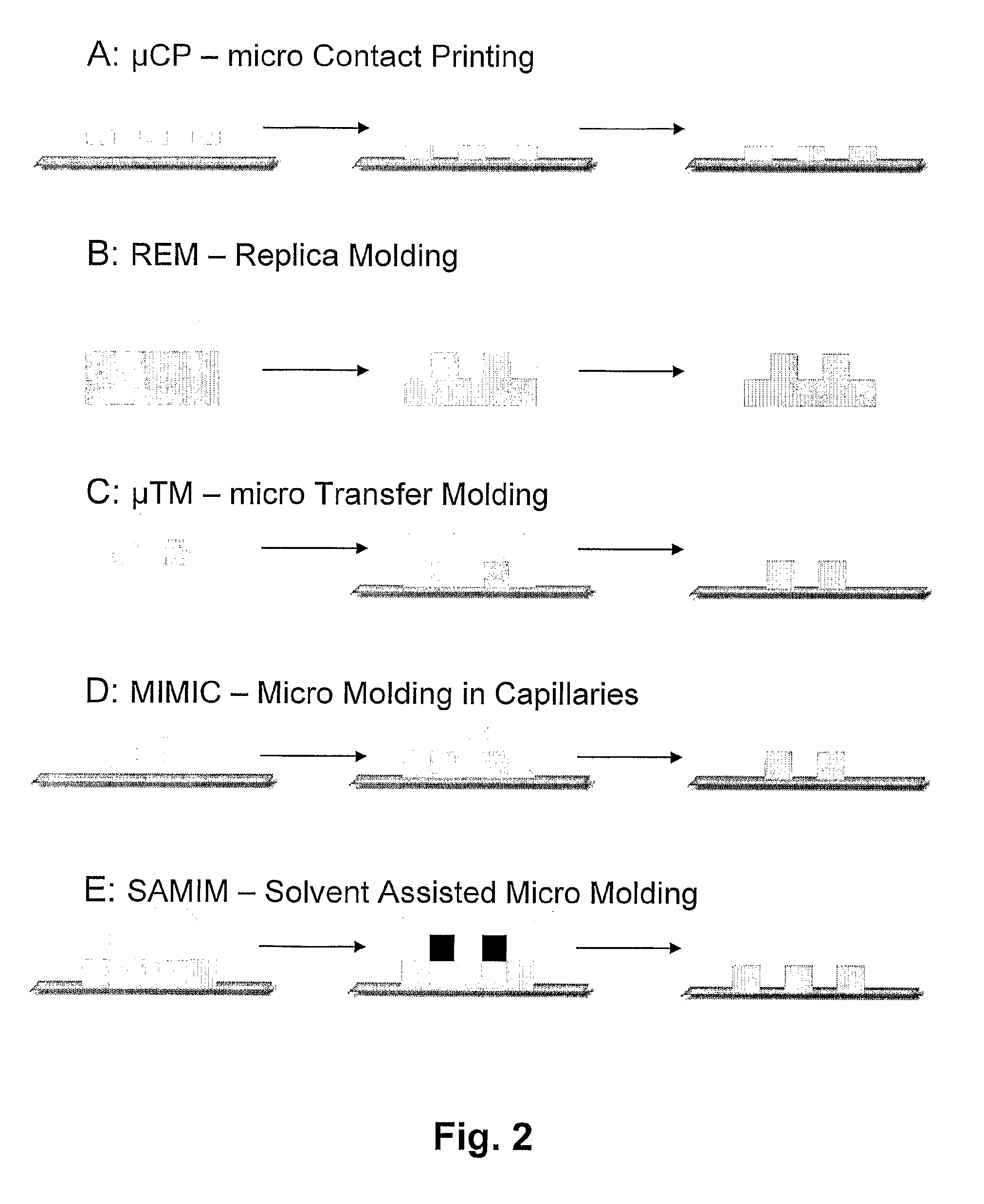
[0014] The present invention is based on the modification of a substrate or surface using soft lithographic methods, microcontact printing (μCP) in particular. Surface or substrate modification using μCP on selected areas is a process that minimizes the waste material since only the modified area needs to be covered with the bioreactive material, such as receptor and reporter molecules. This is useful when the sample amount is sparse or expensive. It is also possible to print over large areas.
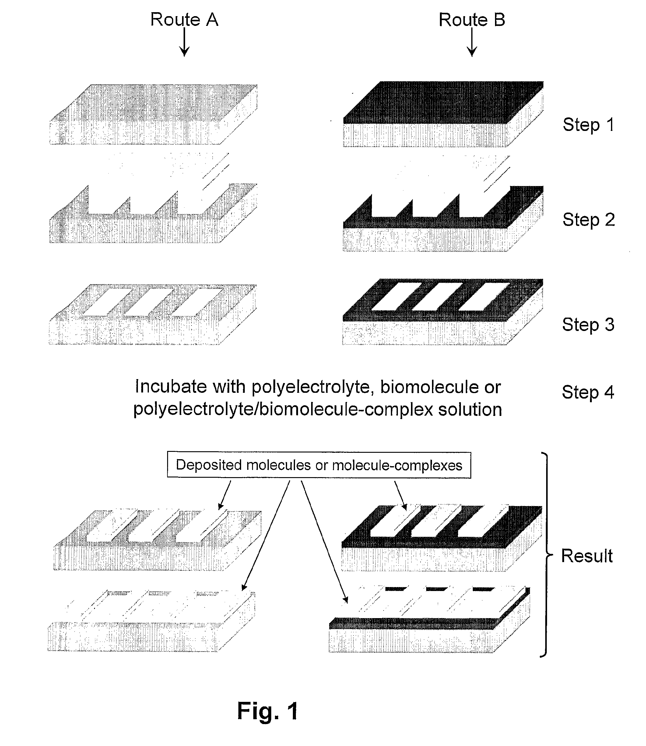
[0016] In one embodiment, the use of different solvents such as water, methanol, water / methanol blends or by using different biomolecules in complex with the conjugated polyelectrolyte, can make the polyelectrolyte stick to different areas on the substrate surface depending on whether it has been in contact with the stamp material or not.

Problems solved by technology

This type of processing typically involves photolithographic and etching techniques which require expensive equipment and is time consuming, and in most cases cannot accommodate biological molecules or water soluble polymers.
This poses some problems with chemical compatibility of biomaterials or certain polymers.
Methods, which use standard photolithography and aggressive chemicals or polymers unreactive towards biosensing, such as PEDOT / PSS, are not attractive ways to produce biosensors.
The method requires gold as substrate which is, in most cases, unwanted in the final biosensor device since most detection principles are based on photoluminescence, which is strongly quenched at metal surfaces.
The chemical step involved in the transfer of the self-assembled monolayer is also unwanted since it makes the construction of the biosensor more difficult.

Method used


Image

  • Patterning Method For Biosensor Applications And Devices Comprising Such Patterns
  • Patterning Method For Biosensor Applications And Devices Comprising Such Patterns
  • Patterning Method For Biosensor Applications And Devices Comprising Such Patterns

Examples


example 2

Immobilization of a Zwitterionic Conjugated Polyelectrolyte / DNA Complex From Water Solution (Route A)

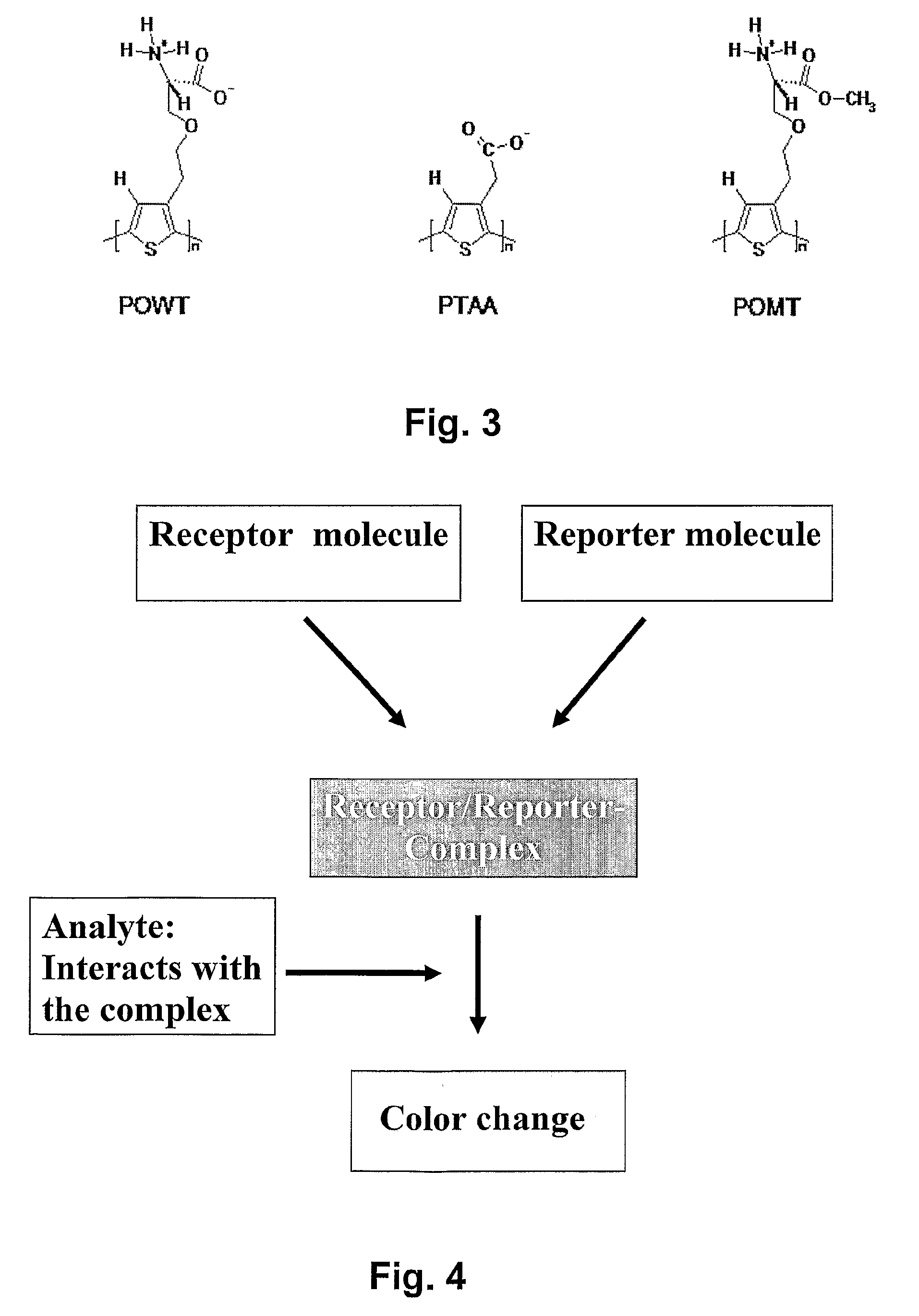
[0094] Stamps and substrates are provided according to VI in the detailed description of the present invention. The surface of the individual substrates is patterned, with respect to surface free energy, by placing separate stamps onto them and incubating for 30 min. Stock solutions containing POWT (0.2 mg / ml) / single stranded DNA (2 / 1 on monomer basis) complex in phosphate buffer (20 mM, pH 7) and POWT (0.2 mg / ml) / double stranded DNA (2 / 1 on monomer basis) complex in phosphate buffer (20 mM, pH 7) was then prepared and incubated for 5 minutes. 30 μl of the solutions was placed on individual patterned surfaces. After 20 minutes of incubation at ambient conditions the individual droplets were removed by blowing with nitrogen gas until the substrates is completely dry. The fluorescence was recorded with an epifluorescence microscope (Zeiss Axiovert inverted microscope A200 Mot) equippe...

example 3

Immobilization of a Zwitterionic Conjugated Polyelectrolyte / Peptide Complex From a Buffered Water Solution (Route A)

[0095] Stamps and substrates are provided according to VI in the detailed description of the present invention. The surface of the individual substrates is patterned, with respect to surface free energy, by placing separate stamps onto them and incubating for 30 min. Stock solutions containing POWT (0.5 mg / ml) / poly-glutamic acid (0.5 mg / ml) in phosphate buffer (20 mM, pH 7) solution and POWT (0.5 mg / ml) / poly-lysine (0.5 mg / ml) in phosphate buffer (20 mM, pH 7) was then prepared and incubated for 5 minutes. 30 μl of the solutions was placed on individual patterned surfaces. After 20 minutes of incubation at ambient conditions the individual droplets were removed by blowing with nitrogen gas until the substrates is completely dry. The fluorescence was recorded with an epifluorescence microscope (Zeiss Axiovert inverted microscope A200 Mot) equipped with a CCD camera (Ax...

example 4

Modification of a POWT Coated Glass Substrate and Transfer of DNA to a Zwitterionic Conjugated Polyelectrolyte (Route B)

[0096] Stamps and substrates are provided according to VI in the detailed description of the present invention. The surface of the individual substrates is patterned, with respect to surface free energy, by placing separate stamps onto them and incubating for 30 min. A stock solution containing POWT (0.5 mg / ml) in water solution was then prepared and incubated for 30 minutes. 50 μl of the solution was placed on a clean glass surface. After 20 minutes of incubation at ambient conditions the droplet were removed by blowing with nitrogen gas until the substrate is completely dry. Then a patterned PDMS stamp was placed on the uniform POWT layer and a picture was taken. After this step, a drop containing single stranded DNA (5 nmol / ml) was placed on the modified POWT and incubated for 20 min and then removed by blowing with nitrogen gas. The fluorescence was recorded w...


PUM

PropertyMeasurementUnit
Massaaaaaaaaaa
Resonance energyaaaaaaaaaa
Elasticityaaaaaaaaaa

Abstract

A patterned substrate for biosensing applications, wherein the pattern includes hydrophilic and hydrophobic areas, and selected ones of the areas include at least at least one reporter molecule, a property of which is detectable. A method of making a patterned substrate includes performing a stamping procedure to provide a pattern of hydrophilic and hydrophobic areas on a substrate of a suitable material. One step of the stamping procedure includes attaching at least one reporter molecule to at least selected ones of the areas, the fluorescence of the conjugated polyelectrolyte being detectable and which will change as a result of interaction with a biomolecule.

Description

FIELD OF THE INVENTION [0001] The present invention relates to a method for patterning a biosensing layer, and to devices, such as biosensors or biochips, which can be made using the method. The devices made according to the invention are particularly suited for methods for detection of biomolecular interactions in materials based on photoluminescent conjugated polyelectrolytes. BACKGROUND OF THE INVENTION [0002] The development of biosensor or biochip devices capable of selectively detecting biomolecular interactions using conjugated polymers (CPs) has attracted a lot of attention in recent years. CPs such as poly(thiophene) or poly(pyrrole) can be utilized to detect many kinds of analyte / receptor interactions, thus enabeling the manufacture of a variety of different biosensor devices. One condition for being able to use CPs for the detection of molecules in biological samples is that the CPs are compatible with an aqueous environment. Conjugated polyelectrolytes offer possibilitie...

Claims


Application Information

Patent Timeline
IPC IPC(8): C12Q1/70C12Q1/68G01N33/53G01N33/554G01N33/569C12M3/00B01L3/00C40B40/06C40B40/10C40B60/14G01NG03F7/00
CPCB01J2219/00382B01J2219/00527B01J2219/00659B01J2219/00722B01J2219/00725B01J2219/00734C40B60/14B01L3/5088B01L2300/0819B01L2300/165B82Y30/00C40B40/06C40B40/10B01L3/5085
Inventor ASBERG, PETERNILSSON, PETERINGANAS, OLLE
Owner BIOCHROMIX
Learn More