Cutting tool insert with molded insert body

a technology of insert body and cutting tool, which is applied in the direction of gear teeth, manufacturing tools, manufacturing apparatus, etc., can solve the problems of labor-intensive brazing process, process, and inability to use superabrasives in many applications, and achieve labor-intensive brazing process, labor-intensive and often costly problems

Inactive Publication Date: 2007-09-06
DIAMOND INNOVATIONS INC
View PDF29 Cites 36 Cited by
  • Summary
  • Abstract
  • Description
  • Claims
  • Application Information

AI Technical Summary

Benefits of technology

[0023]In certain embodiments, the at least one abrasive tip further includes protrusions, depressions, mixtures thereof or other geometric features that aid in securing the abrasive tip to insert body.

Problems solved by technology

However, due to material and / or other costs, use of superabrasive materials may be impractical in many applications.
Although prior art brazing processes do reduce the material cost of manufacturing superabrasive inserts, the process, and in particular the brazing operation itself; is labor intensive and often costly.
The brazing process is labor intensive because the operator has to pay close attention to the joint interface, for example the abrasive cutting edge, the braze interface layer, and the insert body need to be aligned accurately, so as to assure sufficient bonding when the materials are molten.
Another difficulty in the brazing process is that cutting tool materials of different composition or grain size frequently require different brazing conditions, such as, temperatures, times, and braze metal formulations.
PCBN and PCD are known to be difficult to wet with brazes unless active metals, such as Ti or Fe, are incorporated into the metal formula.
They also require the use of higher temperatures that may in turn lead to degradation of the superabrasive material.
A further disadvantage of conventionally brazed inserts is that once formed, then cannot be heated above the sublimation or liquids temperature of the braze metal in subsequent processing steps, such as, for example, chemical vapor deposition (CVD) coating of the insert.
Low melting metals used in braze alloys, for example, Sn and Zn, are volatile and the braze bond may be impaired and / or vacuum components may be contaminated by thermal treatment after brazing.
Moreover, damage to the abrasive cutting edge or insert body from the thermal expansion / contraction cycle during brazing is possible, thereby requiring brazing temperature and time to be kept to a minimum.
In some cases, rebrazing cutting edges to correct braze flaws or regrind cutting edges is not possible.
Furthermore, heat generated at the cutting edge during cutting may damage the braze attachment, allowing the cutting edge to displace in the holder, thereby disrupting the cutting operation.
However, the cutting element described in the '323 patent is limited to hard metals such as stellites.
Operating at higher cutting speeds results in a rapid increase in temperature in the cutting zone.
Such hard metal cutting tools have limited hot-hardness (hardness at elevated temperature) and can only be used for cutting temperatures Lip to 550° C.
However, one limitation of this method when applied to superabrasive or ceramic cutting tools consisting of an abrasive tip attached to insert body by means of brazing, welding or other temperature assisted joining processes is that it increases the likelihood of abrasive tip-insert body joint softening leading to eventual separation.

Method used


Image

  • Cutting tool insert with molded insert body
  • Cutting tool insert with molded insert body
  • Cutting tool insert with molded insert body

Examples


example 1

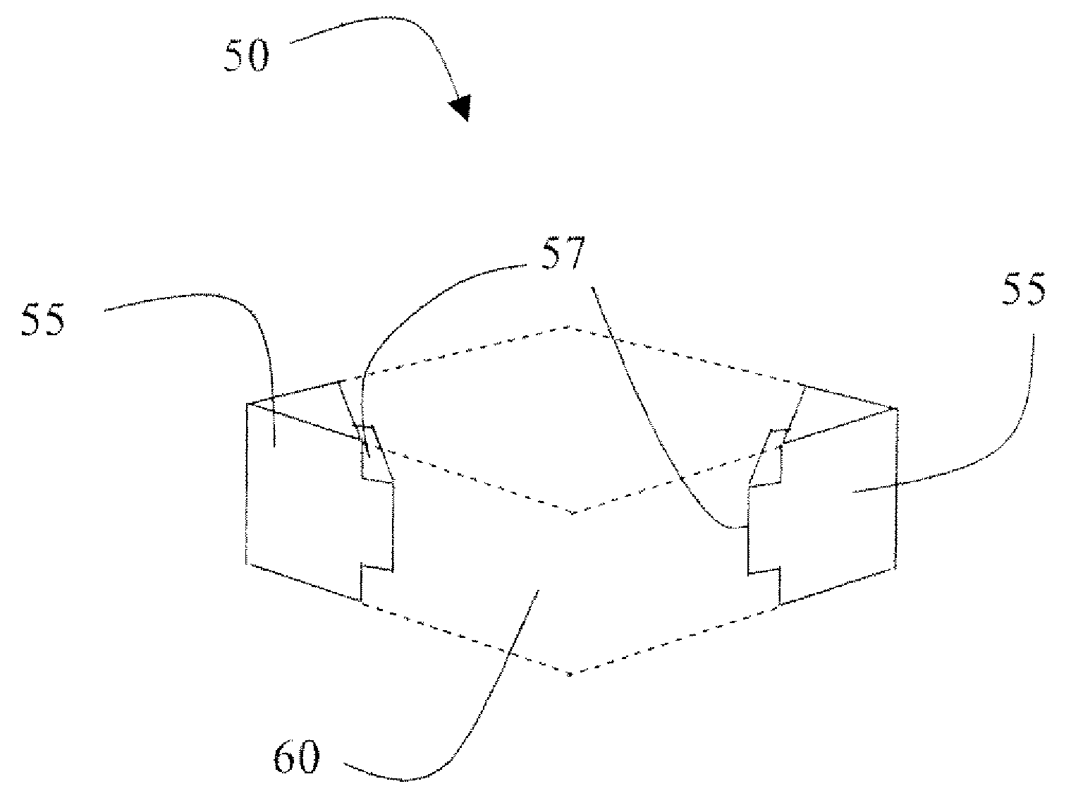
[0078]Diamond-shaped CNUA43 cutting inserts were molded by the method described above using a thermosetting melamine phenolic resin (Plenco grade 0641 glass-fiber and mineral filled). A hard steel mold containing spring-loaded pins was used. The abrasive tip(s) were HTM 2100 material (Diamond innovations Inc.). HTM 2100 comprises 0.5-1 mm of hard PCBN composite bonded to about 1.5 to 2 mm of sintered tungsten carbide. The 80 degree trapezoidal cutting blanks were EDM Cut with radius at the cutting blank to 0.008″ to provide a seal for the flowable resin. The cutting blanks were prepared to provide adequate contact with the curable resin to improve adhesive attachment. The cutting blanks were placed into the cavity comprising the mold and located via small pins. Preheated resin was then pressurized into the mold and flowed over and around the cutting blanks. A seal was made and pressure increased. The mold was heated and time was allowed for complete mold fill, removal of air, resin ...

example 2

[0082]Table 1 illustrates a table of cutting tool performance as measured by inches of steel cut divided by 0.001″ inches of flank wear to the insert cutting blank. Inserts of the present invention prepared from PCBN composite abrasive edges and filled melamine phenolic resin were tested against brazed inserts in continuous facing of hard 52100 and notched hard 4340 steels. In all cases, no cutting blank attachment issues were identified. The cutting blank material, not the molded body material, determined insert performance.

TABLE 1PerformancePerformance(in / 0.001″ flank wear)(in / 0.001″ flank wear)Cutting ConditionsInsert-Molded CuttingStandard Cuttingspeed (feet / min); feedTool InsertTool InsertSteel Type(in / rev); depth-of-cut (in); dry58366897 4340361; 0.005; 0.0160777153HRC 48–52V-notched(interruption)60728552HRC 48–52361; 0.005; 0.01V-notched(interruption)96371179552100324; 0.003; 0.01HRC58–60Facing10309826752100324; 0.003; 0.01HRC58–60Facing95639962

example 3

[0083]The above ground plastic molded insert was metallized with about 2 microns of electroless nickel via a standard Solution process by Diamond Innovations, Inc. The electroless nickel coating was confirmed conductive. In a machining test, the metal hard coat as a “hard shell” on the plastic preventing hot chips from eroding the plastic,


PUM

PropertyMeasurementUnit
cutting speedsaaaaaaaaaa
temperaturesaaaaaaaaaa
temperatureaaaaaaaaaa

Abstract

A cutting tool comprising may include at least one abrasive tip that includes an abrasive cutting edge, and an insert body. The insert body includes a moldable material, and the moldable material is adhered to a portion of the abrasive tip.

Description

CROSS-REFERENCE TO RELATED APPLICATIONS[0001]This patent application claims priority to co-pending U.S. provisional patent application No. 60 / 779,532, entitled “Cutting Tool Insert with Molded Insert Body”, and filed on Mar. 6, 2006, the disclosure of which is incorporated herein by reference in its entirety.STATEMENT REGARDING FEDERALLY SPONSORED RESEARCH[0002]Not applicable.NAMES OF PARTIES TO A JOINT RESEARCH AGREEMENT[0003]Not applicable.SEQUENCE LISTING[0004]Not applicable.BACKGROUND[0005]1. Technical Field[0006]The description set forth herein relates generally to cutting tool inserts having a molded insert body and methods of manufacturing cutting tool inserts.[0007]2. Description of the Related Art[0008]Machining, cutting sawing or drilling cutting tools are often provided with removable inserts including conventional materials such as cemented carbides or ceramics (e.g. Si3N4, TiC—Al2—O composites). FIGS. 1A, 1B and 1C depict a conventional insert 10 firmly held and locked ...

Claims


Application Information

Patent Timeline
Patent Type & Authority Applications(United States)
IPC IPC(8): B23F21/03
CPCB23B27/145B23B27/20B23B2222/61B23B2226/125B23B2226/18B29C45/14336B23B2226/315B23B2226/61B23D61/04B23P15/28B29C45/14311B23B2226/31B23F21/03B23F21/00
Inventor WEBB, STEVEN
Owner DIAMOND INNOVATIONS INC
Why Eureka
Try Eureka