Phosphor, process for producing phosphor and luminescent device

a technology of phosphor and light-emitting device, which is applied in the direction of discharge tube/lamp details, discharge tube luminescnet screen, silicon compound, etc., can solve the problems of poor dispersibility of phosphor particles, inability to obtain high luminance, compact light-emitting layer, etc., and achieve high emission luminance, good light-emitting properties, and high packing density

Inactive Publication Date: 2007-09-13
KK TOSHIBA
View PDF2 Cites 3 Cited by
  • Summary
  • Abstract
  • Description
  • Claims
  • Application Information

AI Technical Summary

Benefits of technology

[0019] The present invention has been made in view of the above circumstances and provides a green phosphor, which is compact and has high packing density, capable of obtaining light emission with high luminance. And, it provides a method for producing a phosphor that it is made possible to decrease an afterglow time while suppressing the luminance of the manganese activated zinc silicate phosphor from lowering. Besides, it provides a light emission display device such as a PDP or an FED excelling in luminance characteristics and display characteristics.
[0020] The present inventors have conducted repeated studies on the production of a manganese activated zinc silicate phosphor and found that almost spherical particles with a major-to-minor axis ratio of 1.0 to 1.4 could be obtained by burning the phosphor material by a rotary heating furnace. And, they found that the afterglow time can be shortened without degrading the luminance by burning the material for the manganese activated zinc silicate phosphor by the rotary heating furnace and completed the present invention.
[0027] The phosphor of the invention comprises a manganese activated zinc silicate phosphor, and it is comprised of almost spherical particles having a major-to-minor axis ratio of 1.0 to 1.4, so that a homogeneous and compact phosphor layer with high packing density can be obtained. Therefore, when this phosphor is used to form a green phosphor layer, a PDP with high emission luminance upon excitation by vacuum ultraviolet rays and good light-emitting properties can be obtained. And, a phosphor layer having high emission luminance upon excitation with low-voltage electron beams having an acceleration voltage of 15 kV or less and excelling in surface smoothness and flatness can be formed, so that an FED having high luminance and excelling in voltage resistance characteristic can be obtained.
[0028] According to the producing process of the invention, the phosphor material are heated in a heating furnace while being flown or rotated by a rotating motion or the like of the furnace about its axis and efficiently applied with uniform thermal energy from the entire outer circumference of the phosphor material. As a result, burning can be completed in a shorter time in comparison with a conventional burning method using a crucible, and a manganese activated zinc silicate phosphor having an almost spherical particle shape with a major-to-minor axis ratio of 1.0 to 1.4 and capable of making light emission with high luminance can be obtained.
[0029] According to the invention, the raw material for the manganese activated zinc silicate phosphor is heated while being flown or rotated within a heating furnace by a rotating motion or the like of the furnace about its axis and applied with uniform thermal energy from the entire outer circumference of the raw material. As a result, manganese activated zinc silicate phosphor particles having a homogeneous composition as a whole and good color purity can be obtained. Therefore, in comparison with those obtained by the conventional burning method using a crucible, the afterglow time of light emission caused upon excitation by vacuum ultraviolet rays or excitation with low-voltage electron beams becomes short. And, they have good color purity and sufficiently high luminance.
[0030] And, where a green phosphor layer is formed by using the manganese activated zinc silicate phosphor produced as described above, a PDP having a short afterglow time of green light emission caused upon excitation by the vacuum ultraviolet rays and good light-emitting properties can be obtained. And, where the green phosphor layer is formed by using this manganese activated zinc silicate phosphor, an FED having short afterglow time of green light emission caused upon excitation by low-voltage electron beams and sufficient high luminance can be obtained.

Problems solved by technology

And when it is used to prepare a paste for coating, the phosphor particles are poor in dispersibility, and aggregation tends to occur.
Therefore, a light emitting layer which is compact and has high packing density and high luminance cannot be obtained.
The phosphor layer easily has irregularities (concavities) on its surface, and the irregularities cause irregular reflection of the emitted light, so that there are problems that a loss of light increases to decrease emission luminance and also to cause variations in luminance.
Besides, the phosphor layer tends to have cavities in it and becomes thick to decrease a space volume of a discharge cell, so that there are problems that an ultraviolet dose for excitation of the phosphor decreases and luminance lowers.
But, there is a problem that the phosphor having manganese such as Zn2SiO4:Mn as an activator has a long afterglow time.
Therefore, it is an important issue for the manganese activated zinc silicate phosphor for excitation by vacuum ultraviolet rays that the afterglow time is decreased while suppressing the emission luminance from lowering.
Therefore, there is a problem that it is hard to form a phosphor layer having sufficient thickness.
Besides, the FED has the same basic display principle as that of a cathode ray tube (CRT) and emits light by exciting the phosphor with an electron beam, but the electron beam has an acceleration voltage (excitation voltage) of 3 to 15 kV which is lower than that of the CRT, and an electric current density with the electron beam is high, so that the phosphor for the FED is not being studied fully.
Even if the above phosphor is used for the green light emitting phosphor for the FED, there is a problem that the manganese activated zinc silicate phosphor has a long afterglow time.

Method used


Image

  • Phosphor, process for producing phosphor and luminescent device
  • Phosphor, process for producing phosphor and luminescent device
  • Phosphor, process for producing phosphor and luminescent device

Examples


examples 10 to 18

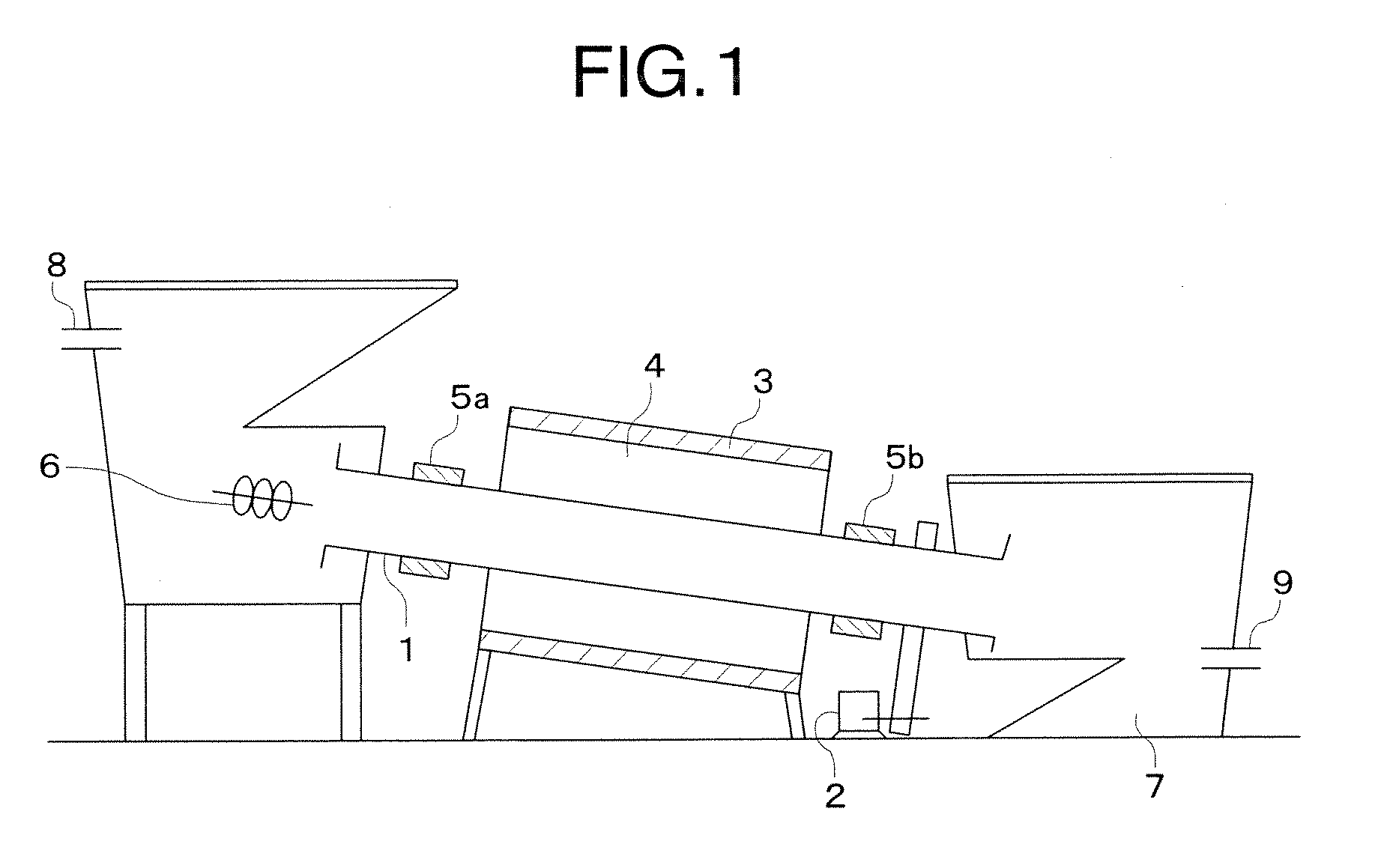
[0098] As phosphor material, 30.0 g of silica (SiO2), 65.0 g of zinc oxide (Zno) and 6.5 g of manganese carbonate (MnCO3) were mixed thoroughly and charged into the heat resistant vessel of the burning apparatus shown in FIG. 1. The heat resistant vessel was disposed at inclined angles of 1 to 5° with respect to the horizontal and rotated about its axis at speeds of 0.5 to 10 rotations per minute. And, the heat resistant vessel had an air atmosphere in it. The phosphor material were heated for burning while being flown or rotated in the heat resistant vessel at temperatures of 1200 to 1250° C. for one to three hours. Heating conditions (heating temperatures, heating time periods, and rotating speeds) of the burning apparatus are shown in Table 2.

[0099] Then, the obtained burned materials were washed with an ion exchange water or the like and dried and, if necessary, sieving or the like was performed to remove coarse particles, and manganese activated zinc silicate phosphors (Zn2SiO...


PUM

PropertyMeasurementUnit
afterglow timeaaaaaaaaaa
acceleration voltageaaaaaaaaaa
wavelengthaaaaaaaaaa

Abstract

A phosphor, comprising a manganese activated zinc silicate phosphor, is comprised of particles having a major-to-minor axis ratio of 1.0 to 1.4. A method for producing the phosphor, comprising burning a phosphor material containing elements constituting a host material of the phosphor and an activator or compounds containing the elements by heating in a heating furnace while flowing or rotating them to manganese activated zinc silicate phosphor particles having a major-to-minor axis ratio of 1.0 to 1.4. Another method for producing the phosphor, comprising burning phosphor material by heating in a heating furnace while flowing or rotating them to obtain a manganese activated zinc silicate phosphor having an afterglow time of less than 9 ms. Thus, a compact phosphor layer with high packing density can be formed, and there can be obtained a phosphor capable of high-luminance green light emission upon excitation by vacuum ultraviolet rays or low-voltage electron beams. Moreover, there can be obtained a manganese-activated zinc silicate phosphor capable of emission of green light of high luminance and short afterglow time upon excitation by vacuum ultraviolet rays or low-voltage electron beams.

Description

TECHNICAL FIELD [0001] The present invention relates to a phosphor, a method for producing the phosphor and a light emitting device, and more specifically to a green phosphor which can be used suitably for display devices such as a plasma display panel (PDP), a field emission display (FED) and the like, a method for producing such a phosphor, and a light emitting device using the phosphor. BACKGROUND ART [0002] Recently, a light emitting device using a vacuum ultraviolet ray having a short-wavelength of 147 nm, 172 nm or the like which is radiated by a discharge of a rare gas is being developed as an excitation source for the phosphor. In Such a light emitting device is used a phosphor which emits light with a vacuum ultraviolet ray as an excitation source, namely a phosphor for excitation by the vacuum ultraviolet ray. The plasma display panel (PDP) is known as a display device using the light emission caused upon excitation by the vacuum ultraviolet ray. [0003] The PDP has propert...

Claims


Application Information

Patent Timeline
Patent Type & Authority Applications(United States)
IPC IPC(8): H01J1/63C01B33/20
CPCH01J2211/42C09K11/595
Inventor YOKOSAWA, NOBUYUKIONO, YUUKIITO, TAKEO
Owner KK TOSHIBA
Why Eureka
Try Eureka