Mechanically induced trapping of molecular interactions

a technology of molecular interactions and mechanical induction, which is applied in the field of microfluidic devices, can solve the problems of increasing the number of measurements needed in an already logistically challenging process, rapid loss of bound material or little bound material, and reducing pressure

Inactive Publication Date: 2007-09-27
CALIFORNIA INST OF TECH
View PDF10 Cites 111 Cited by
  • Summary
  • Abstract
  • Description
  • Claims
  • Application Information

AI Technical Summary

Benefits of technology

[0098] One advantage of the present invention is that molecular interactions that are transient in nature and exhibit nanomolar to micromolar affinities, leading to rapid loss of bound material or little bound material in the first place can be detected and characterized.
[0099] In one aspect the invention provides a method comprising, in a unit cell of a microfluidic device, said unit cell comprising in a liquid environment (a) a substrate (b) a molecular complex comprising a first molecule immobilized in a contact area of the substrate, (c) a second molecule bound to the first molecule and thus indirectly bound to the substrate and (d) a movable element that upon actuation contacts the substrate in the contact area of the substrate; actuating the movable element causing it to contact the substrate in the contact area thereby physically trapping the first and second molecules bound to the substrate in the contact area while substantially expelling solvent and solute molecules. In one embodiment the movable element is an elastomeric trapping membrane.
[0100] In a related aspect the method involves the further step of de-actuating the movable element (e.g., reducing pressure in a membrane actuator chamber so that a button membrane retraces to it undeflected position). Usually the environment is changed prior to de-actuation of the movable element (e.g., any non-bound solute is removed by doing a fluid exchange step).
[0101] After actuating, and/or after deactuating, the movable element measurements can be made of, for example, total, solid phase and/or solution phase concentrations of the interacting molecules (e.g., surface bound protein and bound target DNA in the case of an immobilized DNA-binding protein interacting with a DNA molecule), and dissociation equilibrium constants or other values determined...

Problems solved by technology

However, quantifying the affinity of molecular interactions is a considerable technical challenge.
First, there are often a large number of variables that govern any particular biological interaction.
Therefore obtaining equilibrium dissociation constants, for example, requires one to perform dozens of assays as the concentrations of various components are systematically varied, increasing the number of measurements needed in an already logistically challenging process.
A second and more fundamental problem is the fact that many...

Method used


Image

  • Mechanically induced trapping of molecular interactions
  • Mechanically induced trapping of molecular interactions
  • Mechanically induced trapping of molecular interactions

Examples


example 1

Surface Patterning and MITOMI

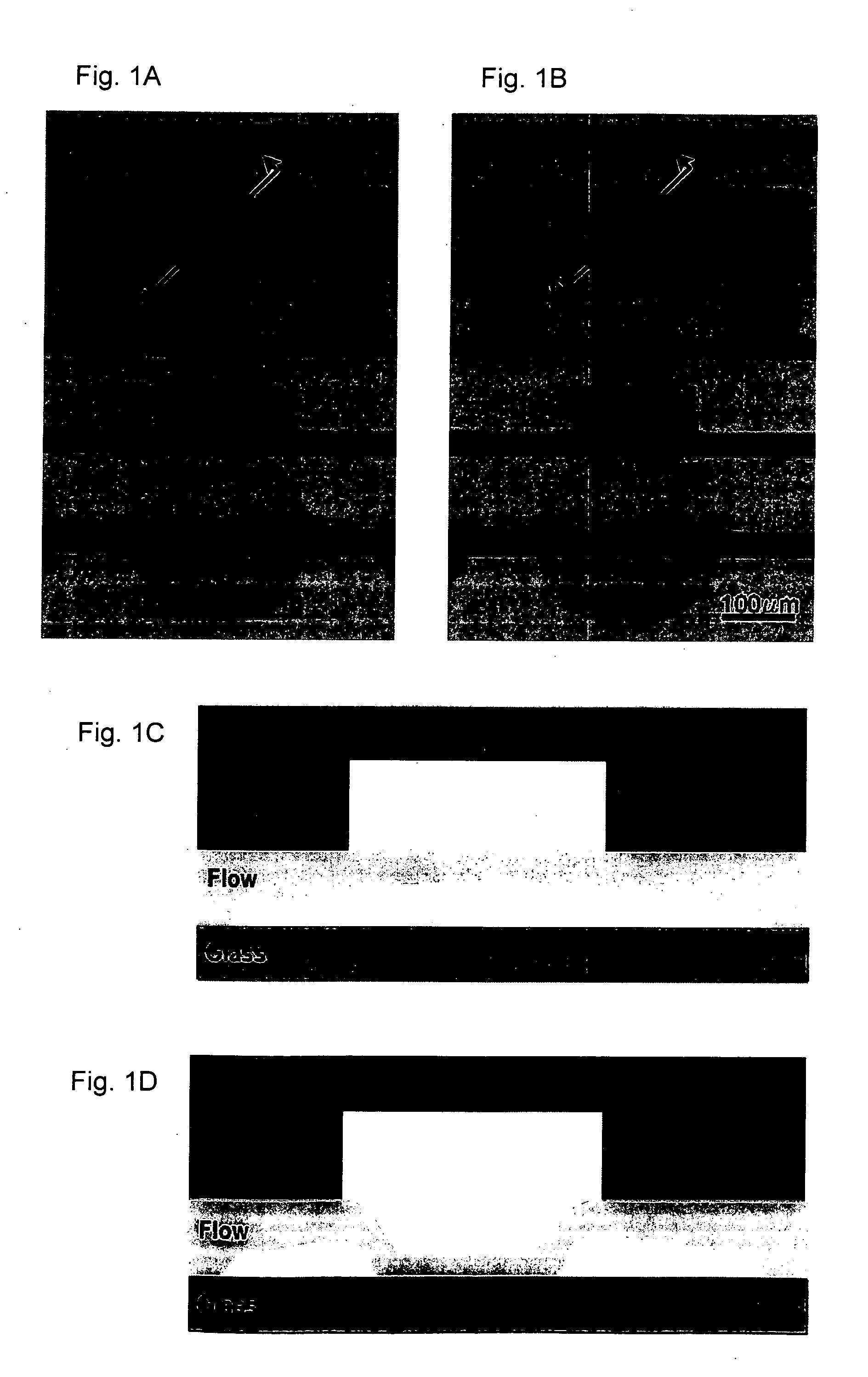
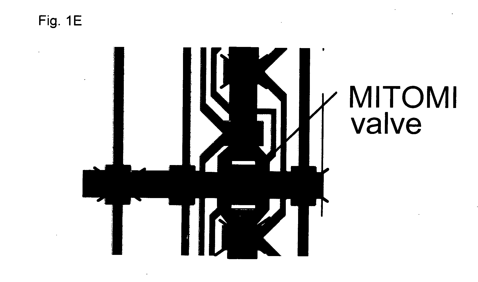
[0141] This example describes a prototypical MITOMI device. A device was fabricated, a protein-based surface chemistry for protein binding was generated, and protein capture and MITOMI were carried out.

[0142] Additionally the effect of varying chamber diameters on the effective surface contacting area was also studied.

Experimental Methods

[0143] A) Flow and Control Mold Manufacturing

[0144] Two 3-inch silicone wafers were treated with hydroxy-methyl silane (HMDS, Sigma) for 2 minutes followed by spin coating with the positive tone photoresist SPR 220-7.0 (Rohm & Haas) in two consecutive spin steps. The first spin step was performed at 500 rpm for 5 seconds followed by 3000 rpm for 60 seconds. The wafers were then soft-baked at 105° C. for 90 seconds. The flow and control patterns were transferred to the molds using two separate transparencies printed with their respective patterns at 20,000 dpi (CadArt). Exposure was done at 365 nm on a MA-6 Mask ali...

example 2

Establishing Detection Sensitivity Levels

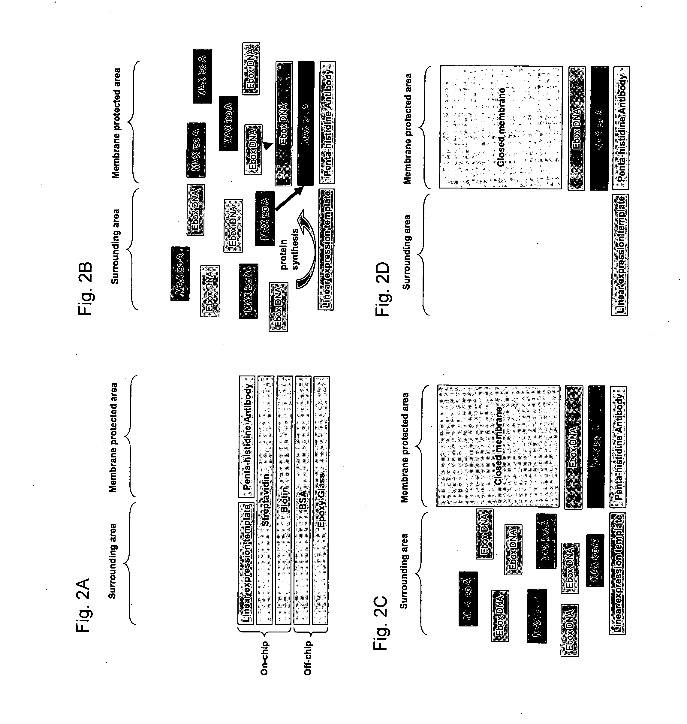
[0155] In order to address the question what the lower detection bounds are for this system we determined at what concentrations non-specific trapping occurs. To do so a device similar to the one described in Example 1 was used. We tested three different Ebox-DNA sequences: Ebox, Er and Enot containing the following E-box binding sequences respectively: CACGTG, CAGGTG and TGATGC. MAX iso A binds the Ebox sequence with a strength in the nanomolar range with decreasing affinities for Er and Enot. Enot binds only non-specifically via interactions with the phosphate backbone and its' affinity is considered negligible falling into the μM regime and considered non-specific. These three sequences when tested in our system return the approximate affinities of 166 nM, 1.3 μM and 23 μM for Ebox, Er and Enot respectively when bound to the surface by a C-terminally 6× Histidine tagged MAX iso A version (FIG. 5). More importantly when MAX iso A without a...

example 3

A Microfluidic Platform to Measure Low Affinity Interactions Enables Comprehensive Characterization of Transcription Factor Binding Energy Landscapes and Prediction of Gene Regulation

[0158] This example describes the use of MITOMI to map the binding energy landscapes of four eukaryotic transcription factors (TFs) belonging to the basic helix-loop-helix (bHLH) family by collecting over 41,000 individual data points from more than 17 devices and covering titrations over 464 target DNA sequences. These binding energy topographies allowed us to 1) predict in vivo function for two yeast TFs, 2) make a comprehensive test of the base additivity assumption, and 3) test the hypothesis that the basic region alone determines binding specificity of bHLH TFs. bHLH motifs represent the third largest TF family in eukaryotes and regulate a wide variety of cellular functions ranging from cell proliferation and development to metabolism. Information in this Example is found in Maerkl S J and Quake S...


PUM

PropertyMeasurementUnit
Pressureaaaaaaaaaa
Areaaaaaaaaaaa
Environmental propertiesaaaaaaaaaa

Abstract

The invention provides devices and methods for surface patterning the substrate of a microfluidic device, and for detection and analysis of interactions between molecules by mechanically trapping a molecular complex while substantially expelling solvent and unbound solute molecules. Examples of molecular complexes include protein-protein complexes and protein-nucleic acid complexes.

Description

CROSS-REFERENCE TO RELATED APPLICATIONS [0001] This application claims benefit of U.S. Provisional Application No. 60 / 762,330 entitled “Mechanically Induced Trapping of Molecular Interactions” and Provisional Application No. 60 / 762,344 entitled “Programming Microfluidic Devices with Molecular Information,” both filed Jan. 26, 2006, and to U.S. Provisional Application No. 60 / ______ entitled “Mechanically Induced Trapping of Molecular Interactions” (Attorney Docket No. 20174C-016210 and U.S. Provisional Application No. 60 / ______ entitled “Programming Microfluidic Devices with Molecular Information” (Attorney Docket No. 20174C-016310), both filed Jan. 11, 2007. The entire content of each of these applications is incorporated herein by reference.STATEMENT REGARDING FEDERALLY SPONSORED RESEARCH [0002] Work described herein has been supported, in part, by the Office of Naval Research (ONR)—Space and Naval Warfare Systems Center (Grant No. N66001-02-1-8929; Subcontract Princeton 341-6260-5...

Claims


Application Information

Patent Timeline
IPC IPC(8): C12Q1/68G01N33/53
CPCB01L2400/0481B01L2400/0655G01N33/5302G01N33/54393B01L3/5027B01J2219/0043B01L3/502738B01L2300/0816B01L2300/0819B01L2300/0861B01L2300/123B01L3/502707G01N33/543
Inventor QUAKE, STEPHEN R.MAERKL, SEBASTIAN J.
Owner CALIFORNIA INST OF TECH
Why Eureka
Try Eureka