Reinforced Surgical Conduit for Implantation of a Stented Valve Therein

Active Publication Date: 2007-10-11
MEDTRONIC VASCULAR INC
View PDF99 Cites 416 Cited by
  • Summary
  • Abstract
  • Description
  • Claims
  • Application Information

AI Technical Summary

Problems solved by technology

Heart valves, such as the mitral, tricuspid, aortic and pulmonary valves, are sometimes damaged by disease or by aging, resulting in problems with the proper functioning of the valve.
Heart valve problems generally take one of two forms: stenosis, in which a valve does not open completely or the opening is too small, resulting in restricted blood flow; or insufficiency, in which blood leaks backward across a valve when it should be closed.
Over time, the right ventricle enlarges, which leads to congestive heart failure (CHF).
In severe cases, the CHF results in clinical symptoms including shortness of breath, fatigue, chest pain, fainting, heart murmur, and in babies, poor weight gain.
Previously, valve repair or replacement required open-heart surgery with its attendant risks, expense, and extended recovery time.
Open-heart surgery also requires cardiopulmonary bypass with risk of thrombosis, stroke, and infarction.
However, as the child grows, the valve can become too small to accommodate the blood flow to the lungs that is needed to meet the increasing energy demands of the growing child, and it may then need to be replaced with a larger va

Method used


Image

  • Reinforced Surgical Conduit for Implantation of a Stented Valve Therein
  • Reinforced Surgical Conduit for Implantation of a Stented Valve Therein
  • Reinforced Surgical Conduit for Implantation of a Stented Valve Therein

Examples


Embodiment Construction

[0031] The invention will now be described by reference to the drawings wherein like numbers refer to like structures.

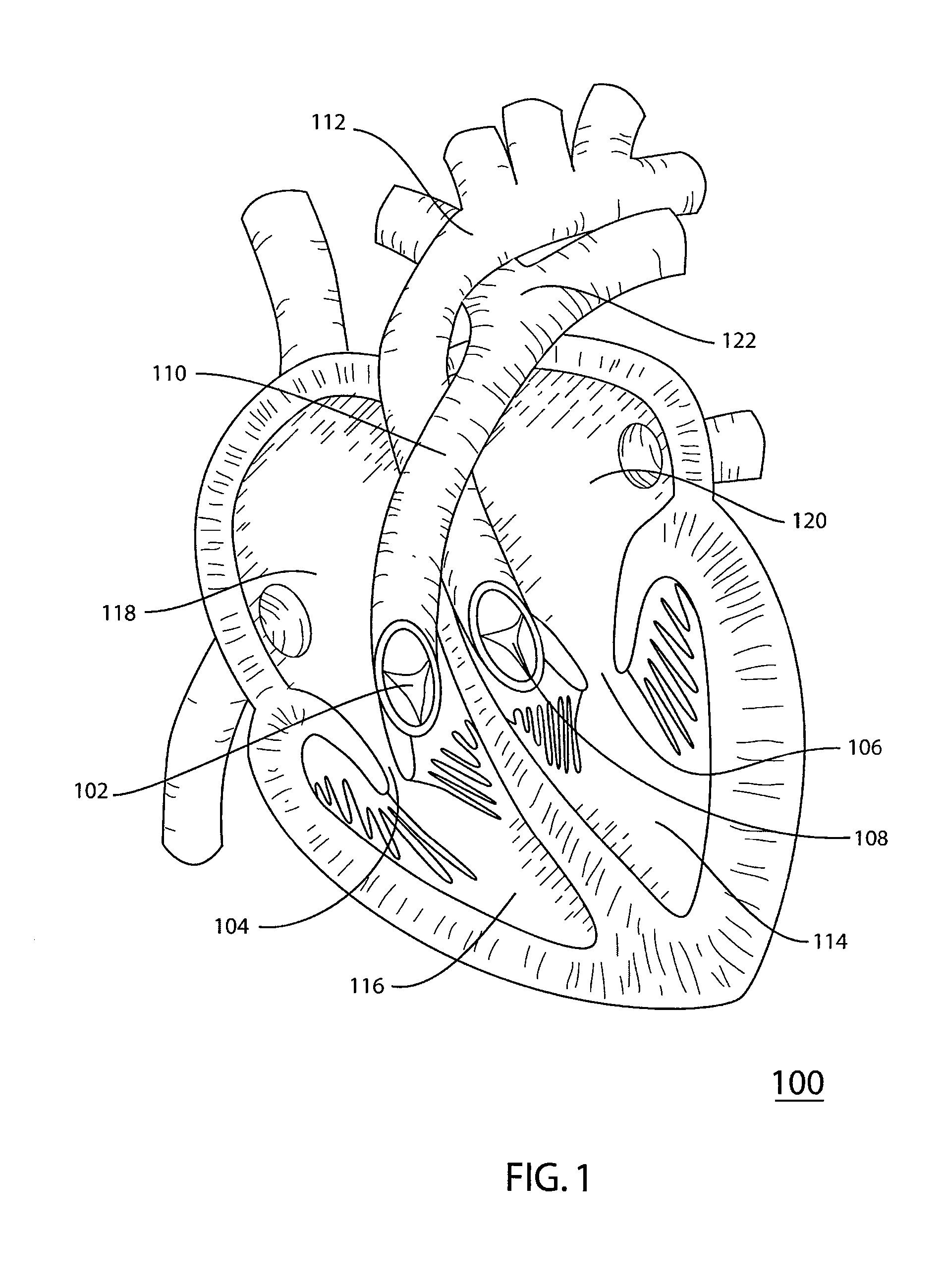
[0032] Referring to the drawings, FIG. 1 is a schematic representation of the interior of human heart 100. Human heart 100 includes four valves that work in synchrony to control the flow of blood through the heart. Tricuspid valve 104, situated between right atrium 118 and right ventricle 116, and mitral valve 106, between left atrium 120 and left ventricle 114 facilitate filling of ventricles 116 and 114 on the right and left sides, respectively, of heart 100. Aortic valve 108 is situated at the junction between aorta 112 and left ventricle 114 and facilitates blood flow from heart 100, through aorta 112 to the peripheral circulation.

[0033] Pulmonary valve 102 is situated at the junction of right ventricle 116 and pulmonary artery 110 and facilitates blood flow from heart 100 through the pulmonary artery 110 to the lungs for oxygenation. The four valves work by op...


PUM


Abstract

A pulmonary valve replacement system having a vascular conduit and a prosthetic valve device including a valve operably connected to a support structure. The prosthetic valve device is positioned within the vascular conduit. A conduit support includes a substantially circular cross-section. The conduit support is positioned adjacent to and reinforces the vascular conduit. In one embodiment, the pulmonary valve replacement system includes a catheter and an inflatable member operably attached to the catheter. The prosthetic valve device is disposed on the inflatable member. The invention provides a method for replacing a pulmonary valve including providing a vascular conduit positioned at a treatment site. The vascular conduit includes a conduit support positioned adjacent the vascular conduit. A prosthetic valve device is deployed within the vascular conduit via catheter. The prosthetic valve device includes a valve operably connected to a support structure. The vascular conduit is supported with the conduit support.

Description

TECHNICAL FIELD OF THE INVENTION [0001] This invention relates generally to medical devices for treating cardiac valve abnormalities, and particularly to a pulmonary valve replacement system and method of operating the same. BACKGROUND OF THE INVENTION [0002] Heart valves, such as the mitral, tricuspid, aortic and pulmonary valves, are sometimes damaged by disease or by aging, resulting in problems with the proper functioning of the valve. Heart valve problems generally take one of two forms: stenosis, in which a valve does not open completely or the opening is too small, resulting in restricted blood flow; or insufficiency, in which blood leaks backward across a valve when it should be closed. [0003] The pulmonary valve regulates blood flow between the right ventricle and the pulmonary artery, controlling blood flow between the heart and the lungs. Pulmonary valve stenosis is frequently due to a narrowing of the pulmonary valve or the pulmonary artery distal to the valve. This narr...

Claims


Application Information

Patent Timeline
IPC IPC(8): A61F2/24A61F2/06A61F2/90
CPCA61F2/06A61F2/2418A61F2/2433A61F2230/0054A61F2/90A61F2250/006A61F2/2475
Inventor BIRDSALL, MATTHEW J.
Owner MEDTRONIC VASCULAR INC
Why Eureka
Try Eureka