Hybrid filter for high slew rate output current application

a technology of output current and hybrid filter, applied in the direction of electric variable regulation, process and machine control, instruments, etc., can solve the problems of unavoidable delay in response, inadequate or impractical current power supply design, and increasing power supply requirements to become much more stringent, so as to reduce capacitance and increase the effective slew rate

Inactive Publication Date: 2007-10-25
VIRGINIA TECH INTPROP INC
View PDF12 Cites 8 Cited by
  • Summary
  • Abstract
  • Description
  • Claims
  • Application Information

AI Technical Summary

Benefits of technology

[0011] In accordance with another aspect of the invention, a method is provided for reducing capacitance required for filtering output of a voltage regulator and/or increasing effective slew rate of said voltage regulator, comprising steps of setting bandwid

Problems solved by technology

Recent developments in many types of electronic devices have caused power supply requirements to become much more stringent to the point that current power supply designs are becoming inadequate or impractical.
However, such feedback involves an unavoidable delay in the response to transient changes in load and limits accuracy of voltage regulation.
The slew rate of current change is also compromised by the total capacitance presented by these filter and decoupling capacitors.
Such effects are particularly evident in regard to current and foreseeable complex digital circuits such as microprocessors or telecommunications devices which operate at extreme clock speeds and where the load can change radically from one clock pulse to the next and parasitic inductance and capacitance of power connections may cause large changes in impedance of the power supply connections.
Moreover, the trend toward increased complexity and reduced size of integrated circuit chips

Method used


Image

  • Hybrid filter for high slew rate output current application
  • Hybrid filter for high slew rate output current application
  • Hybrid filter for high slew rate output current application

Examples


Embodiment Construction

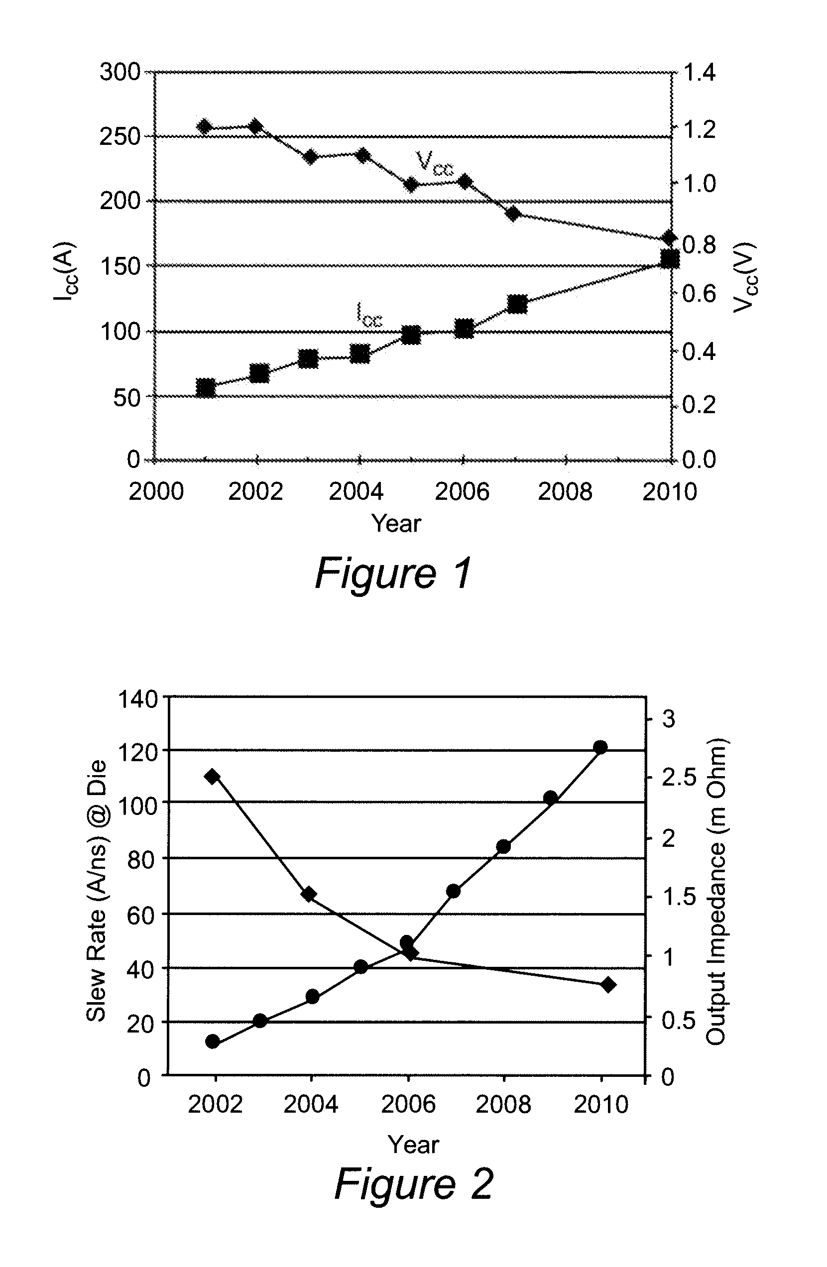
[0029] Referring now to the drawings, and more particularly to FIGS. 1 and 2, there is shown historical and projected future power supply current and voltage requirements and slew rate and output impedance for power supplies of current design for supplying power to microprocessors, respectively. As alluded to above, increases in integration density and reduction of minimum feature size regimes required to provide improvements in performance and functionality of microprocessors in recent years has led to a decrease in power supply voltage (e.g. to improve breakdown margins and to reduce voltage swing to reduce currents to capacitive elements such as gates of field effect transistors) from about 1.2 volts is 2001-2002 to about 1.0 volts at the present time with a further reduction to about 0.8 volts projected within the near future. Such a reduction not only reduces the voltage regulation tolerance (e.g. 10% of rated voltage) but imposes even more stringent requirements for voltage re...


PUM


Abstract

An active linear regulator circuit in parallel with a filter capacitor of a switching voltage regulator injects current to a load only when the switching regulator and capacitor cannot supply adequate current to follow high frequency load transients in a manner which is compatible with adaptive voltage positioning (AVP) requirements. control of current injection and determination of the insufficiency of current from the switching regulator and capacitors is achieved by impedance matching of the linear regulator to the switching regulator. The linear regulator thus operates at relatively low current and duty cycle to limit power dissipation therein. By matching impedances and increasing the bandwidth of the switching regulator, filter capacitor requirements can be reduced to the point of being met entirely by packaging and/or on-die capacitors which may be placed close to or at the point of load to reduce parasitic inductance, as can the linear regulator.

Description

BACKGROUND OF THE INVENTION [0001] 1. Field of the Invention [0002] The present invention generally relates to power supplies for electronic devices and, more particularly, high current, low voltage loads of complex electronic devices such as computers and telecommunications devices which operate at high frequencies. [0003] 2. Description of the Prior Art [0004] Recent developments in many types of electronic devices have caused power supply requirements to become much more stringent to the point that current power supply designs are becoming inadequate or impractical. For example, switching power supplies are well known for DC-DC conversion and operate by switching current from a relatively high voltage source which is then filtered, often using a series inductance, to maintain an approximate desired voltage on a bulk capacitor, often referred to as a filter capacitor. Switching frequency and / or duty cycle to control output voltage is determined by feedback of variation in voltage ...

Claims


Application Information

Patent Timeline
IPC IPC(8): G05F1/00
CPCH02M2001/0045H02M3/158H02M1/0045
Inventor XU, MINGREN, YUANCHENGLEE, FRED C.SCHMIT, ANDREW P.
Owner VIRGINIA TECH INTPROP INC
Why Eureka
Try Eureka