
Solder Paste and Electronic Device Using Same

Inactive Publication Date: 2007-12-06
PANASONIC CORP
View PDF3 Cites 17 Cited by
  • Summary
  • Abstract
  • Description
  • Claims
  • Application Information

AI Technical Summary

Benefits of technology

[0014] This invention provides such solder paste that prevents, when a minute-size passive component or a semiconductor integrated circuit element having a small terminal pitch is soldered by the solder paste, the solder particles from being oxidized to provide highly-reliable solder joint even when the solder paste is used in a very small amount. The solder paste of the present invention is obtained by mixing solder alloy powders with flux and is structured so that the flux has, at a pre-heating temperature in a heating / melting step, a high temperature retention property by which the flux covers the surface of the solder alloy powders.
[0015] This structure prevents the solder alloy powders to be covered by the flux until a pre-heating temperature is reached to prevent the solder alloy powders from being exposed to air. Thus, the surface of the solder alloy powders can be prevented from being oxidized. This prevents, even when the solder paste is used for a 0603-size electronic component using a very small amount of solder paste or a semiconductor integrated circuit element connected with a narrow pitch, a solder ball from being caused to provide highly-reliable joint.
[0017] This structure allows a minute size chip component or a minute pitch semiconductor element or the like, which has conventionally been difficultly packaged with high reproducibility, to be packaged with high reproducibility and in a stable manner. Thus, an electronic device having a smaller size can be realized.

Problems solved by technology

However, an increased package size for accommodating a greater number of terminals is not preferable.
This means a risk where such a small-size electronic component may be soldered with insufficiently-melted solder by conventional soldering conditions under which larger size electronic components have been stably soldered.
In this case, solder balls or the like may be caused and a defective joint may be caused.
The same risk also applies to a semiconductor integrated circuit element.
For example, a problem has been found in which a narrower pitch for coping with an increased number of terminals also requires a smaller soldering area.
Thus, even when most solder particles in the solder paste are melted and are integrated, those solder particles having an oxidized surface are not melted and not integrated to subsequently form a solder ball.
This solder ball causes a short circuit failure or the like.
Furthermore, a minute-size passive component and a semiconductor integrated circuit element having a narrow terminal pitch as described above require a very small amount of solder paste.
Thus, the existence of a solder ball that is not effectively used for a soldering process causes a defective solder or a lower reliability for a soldered portion.
When flux flows during a pre-heating process, the solder particles also flow and diffuse in an area larger than an area to be printed and coated, thereby causing solder sagging.
However, in the case of an ultrasmall component such as a 0603 size passive component, an area coated with solder paste is very small to cause a very small coating amount of solder paste and thus the sagging as described above rarely occurs.
Thus, the only prevention of the sagging may not be able to prevent a solder ball caused in a very small amount of solder.
Although this method is effective for a conventional coating amount of solder paste, this method may not sufficiently prevent the oxidation of a very small coating amount of solder paste because the solder paste in such a small coating amount causes a small amount of nitrogen gas.

Method used


Image

  • Solder Paste and Electronic Device Using Same
  • Solder Paste and Electronic Device Using Same
  • Solder Paste and Electronic Device Using Same

Examples


embodiment 1

Illustrative Embodiment 1

[0054] Solder paste was prepared by flux of 8% by weight and solder alloy powders (Sn—Ag—Cu) of 92% by weight. It is noted that the flux is composed of the following components.

Polymerized rosin52% by weightHydrogenated ricinus 5% by weightDiphenylguanidine HBr 2% by weighta-telpionel33% by weightEpoxy resin 8% by weight

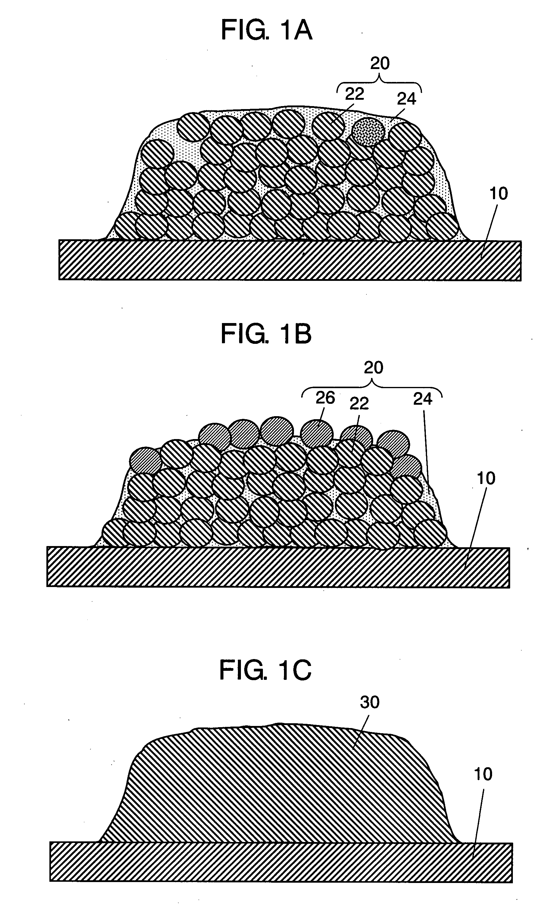
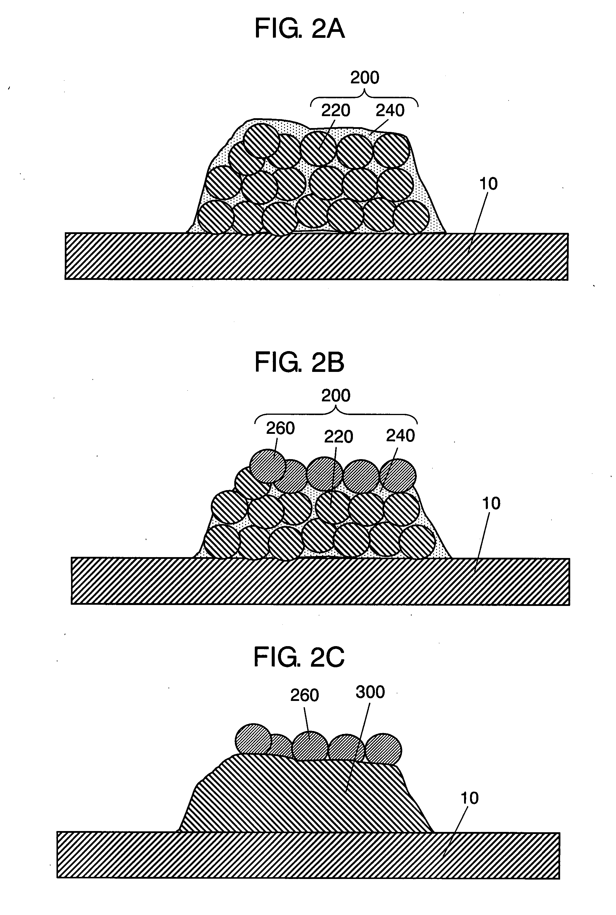
[0055] Furthermore, curing agent of epoxy resin composed of acid anhydride and polyamide was added in a required amount to the solder paste. This provides the solder paste with a viscosity adjusted so that the flux covers the surface of solder particles even when at a pre-heating temperature during a reflow soldering operation.

embodiment 2

Illustrative Embodiment 2

[0056] Solder paste was prepared by flux of 10% by weight and solder alloy powders (Sn—Ag—Cu) of 90% by weight. It is noted that the flux is composed of the following components.

Polymerized rosin46% by weightStearylamide 4% by weightCyclohexylamine HBr 2% by weighta-telpionel40% by weightPolyester resin 8% by weight

[0057] Furthermore, curing agent of polyester resin in which benzoyl peroxide and lauryl peroxide are added with an appropriate amount of catalyst such as cobalt naphthenate. This provides, as in Illustrative Embodiment 1, the solder paste with a viscosity adjusted so that the flux covers the surface of solder particles even when at a pre-heating temperature during a reflow soldering operation.

embodiment 3

Illustrative Embodiment 3

[0058] Solder paste was prepared by flux of 8% by weight and solder alloy powders (Sn—Ag—Cu—Bi) of 92% by weight. It is noted that the flux is composed of the following components.

Polymerized rosin40% by weightHydrogenated ricinus 5% by weightDiphenylguanidine HBr 2% by weighta-telpionel23% by weightButyl carbitol20% by weightStyrene monomer10% by weight

[0059] Furthermore, curing catalyst of styrene monomer composed of benzoyl peroxide was added to the solder paste. This provides, as in Illustrative Embodiment 1 and Illustrative Embodiment 2, the solder paste with a viscosity adjusted so that the flux covers the surface of solder particles even when at a pre-heating temperature during a reflow soldering operation.


PUM


Abstract

This invention provides such solder paste that prevents, when a minute-size passive component or a semiconductor integrated circuit element having a small terminal pitch is soldered by the solder paste, the solder particles from being oxidized to provide highly-reliable solder joint even when the solder paste is used in a very small amount. Specifically, solder paste obtained by mixing solder alloy powders with flux is structured so that the flux has, at a pre-heating temperature in a heating / melting step, a high temperature retention property by which the flux covers the surface of the solder alloy powders.

Description

TECHNICAL FIELD [0001] The present invention relates to solder paste used in the field of electronic devices. In particular, the present invention relates to solder paste for subjecting minute electronic components to solder joint to various substrates and an electronic device using the solder paste. BACKGROUND ART [0002] Recently, for the purpose of providing an electronic device having a smaller size and a lighter weight, a technique has been used that uses solder paste to package, with a high density, a surface-mounted electronic component on a print wiring substrate having thereon a fine pattern. [0003] This technique uses such solder paste that is prepared by mixing about 80 to 90% by weight solder fine powders having a particle size of few dozens of μm and about 10 to 20% by weight flux consisting of rosin, solvent, activator, thixotropic agent or the like to provide paste-like mixture. This solder paste has a viscosity adjusted to be suitable for a screen printing. [0004] Sol...

Claims


Application Information

Patent Timeline
IPC IPC(8): B23K35/34
CPCB23K35/0244B23K35/262B23K35/3613H05K2203/111H05K3/3484H05K3/3489H05K2201/0224B23K35/362H05K3/3485
Inventor TSUKAHARA, NORIHITONISHIKAWA, KAZUHIRO
Owner PANASONIC CORP
Features
  • Generate Ideas
  • Intellectual Property
  • Life Sciences
  • Materials
  • Tech Scout
  • Unparalleled Data Quality
  • Higher Quality Content
  • 60% Fewer Hallucinations
Learn More