Method of forming a porous nickel coating, and related articles and compositions

Inactive Publication Date: 2007-12-06
GENERAL ELECTRIC CO
View PDF11 Cites 28 Cited by
  • Summary
  • Abstract
  • Description
  • Claims
  • Application Information

AI Technical Summary

Problems solved by technology

However, the high cost of these materials encourages researchers to find alternative electrocatalysts with efficiency comparable to the efficiency of platinum-based electrocatalysts.
The only drawback of hydrogen-based fuels is that hydrogen

Method used


Image

  • Method of forming a porous nickel coating, and related articles and compositions
  • Method of forming a porous nickel coating, and related articles and compositions
  • Method of forming a porous nickel coating, and related articles and compositions

Examples


example 1

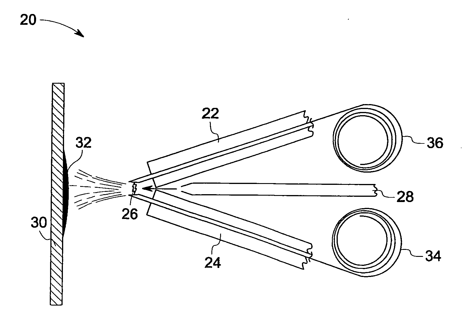
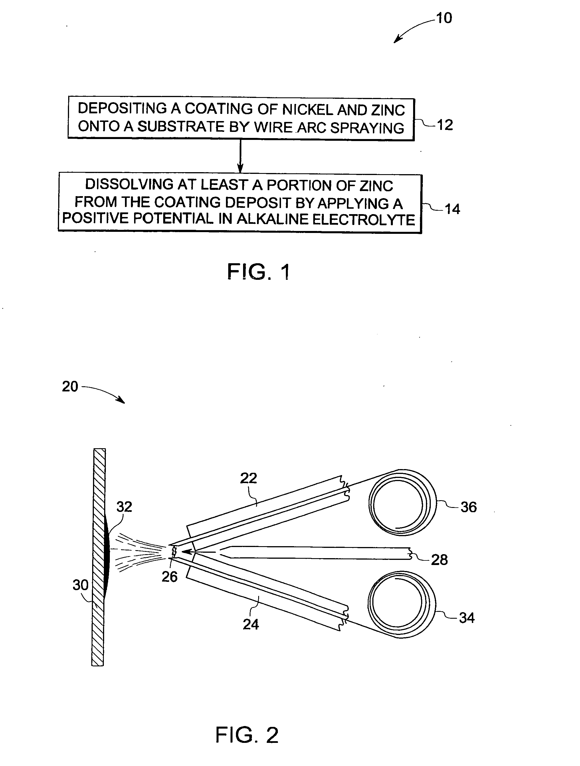
[0053]Sample Preparation: Porous Ni-Based Coatings by Twin Arc Spray Process

[0054]A wire arc coating of Ni based alloys on Microcell cathodes cut from stainless steel 304 sheet with thickness of about 1.6 millimeters was formed, using a SmartArc-350PP Electric Arc Spray System manufactured by Sulzer Metco. Zinc was co-sprayed with Ni and Ni-based alloys by feeding two wires made of these materials into the spray system. For comparison, a set of samples was prepared by co-spraying nickel along with aluminum. The coating thickness was about 114 microns to about 228 microns after 3 passes.

[0055]Zinc Leaching:

[0056]To determine optimal conditions for leaching, different procedures were tested: hot leaching included leaching at 80° C., and cold leaching included leaching at 25° C. Leaching outside the cell included leaching overnight in a beaker with 30% KOH, while cold in-cell leaching included leaching overnight at 25° C. in an assembled cell, and hot in-cell leaching, included leachin...


PUM

PropertyMeasurementUnit
Fractionaaaaaaaaaa
Percent by massaaaaaaaaaa

Abstract

A method of forming a porous nickel coating is provided. The method includes the steps of: depositing a coating onto a substrate by melting and atomizing two consumable electrode wires of a selected composition in a wire-arc spray device, so as to form a molten, atomized material, and directing the material to the substrate to form a coating deposit; the selected composition including nickel and a sacrificial metal; and then dissolving at least a portion of the sacrificial metal from the coating deposit by applying a positive potential in an alkaline electrolyte, so as to obtain a porous nickel coating. An electrolytic cell that includes a porous nickel coating is also described.

Description

STATEMENT REGARDING FEDERALLY SPONSORED RESEARCH & DEVELOPMENT[0001]This invention was made with Government support under contract number DE-FC36-04GO14223 awarded by DOE. The Government has certain rights in the invention.BACKGROUND OF THE INVENTION[0002]The invention is related to a method of forming a nickel coating. More particularly, the invention is related to a wire-arc spray coating method of making a porous nickel coating, e.g., a coating which comprises Raney nickel. The invention is also related to an electrode, comprising a porous nickel coating.[0003]Electrocatalysts are extensively used in alternative fuels production (e.g., hydrogen): production of crude oil and gas from non-conventional sources such as tar sands and heavy oil reservoirs: synfuels production (e.g., coal liquefaction / gasification, shale oil). Electrocatalysts are also useful in oil recycling, and other emerging energy technologies such as fuel cells and photovoltaic cells. They are also employed in var...

Claims


Application Information

Patent Timeline
IPC IPC(8): C25F1/00C25B1/02
CPCC25B1/02C25B11/035C25F3/14Y02E60/50H01M4/98H01M8/1011H01M2008/1095H01M4/8885C25B11/031
Inventor ROSENZWEIG, LARRY STEVENSOLOVEICHIK, GRIGORII LEVZAPPI, GUILLERMO DANIEL
Owner GENERAL ELECTRIC CO
Why Eureka
Try Eureka