Thin film transistor substrate and display device

a thin film transistor and substrate technology, applied in semiconductor devices, semiconductor/solid-state device details, instruments, etc., can solve the problems of reducing on-current, increasing leak current, and significantly deteriorating semiconductor silicon semiconductor performance, so as to prevent a bad effect on the tft element

Inactive Publication Date: 2007-12-06
KOBE STEEL LTD
View PDF5 Cites 43 Cited by
  • Summary
  • Abstract
  • Description
  • Claims
  • Application Information

AI Technical Summary

Benefits of technology

[0009]The reason for interposing the barrier metal between the wiring metal (source electrode or drain electrode) and the TFT element (silicon layer) is to prevent a bad effect on the TFT element when pure Al or Al alloy configuring the wiring is directly contacted to the semiconductor layer of the TFT element. Amorphous silicon or polycrystalline silicon is used for the semiconductor layer. A generation mechanism of the bad effect on the TFT element is as follows.

Problems solved by technology

When Al atoms are thermally diffused into the semiconductor silicon, semiconductor performance of the semiconductor silicon is significantly deteriorated.
This induces increase in leak current, decrease in on-current, reduction in switching speed and the like, consequently desired switching performance is hardly obtained.
Similarly, when Si atoms are diffused into wiring, semiconductor performance of the silicon semiconductor is deteriorated, consequently deterioration in switching performance is induced.
That is, display performance or quality of a display is reduced.

Method used


Image

  • Thin film transistor substrate and display device
  • Thin film transistor substrate and display device
  • Thin film transistor substrate and display device

Examples


examples

[0038]Hereinafter, examples of the invention and a comparative example are described. The invention is not limited to the examples, and can be carried out with being appropriately altered and modified within a scope suitable for the purport of the invention, and all of such alterations and modifications are included in a technical scope of the invention.

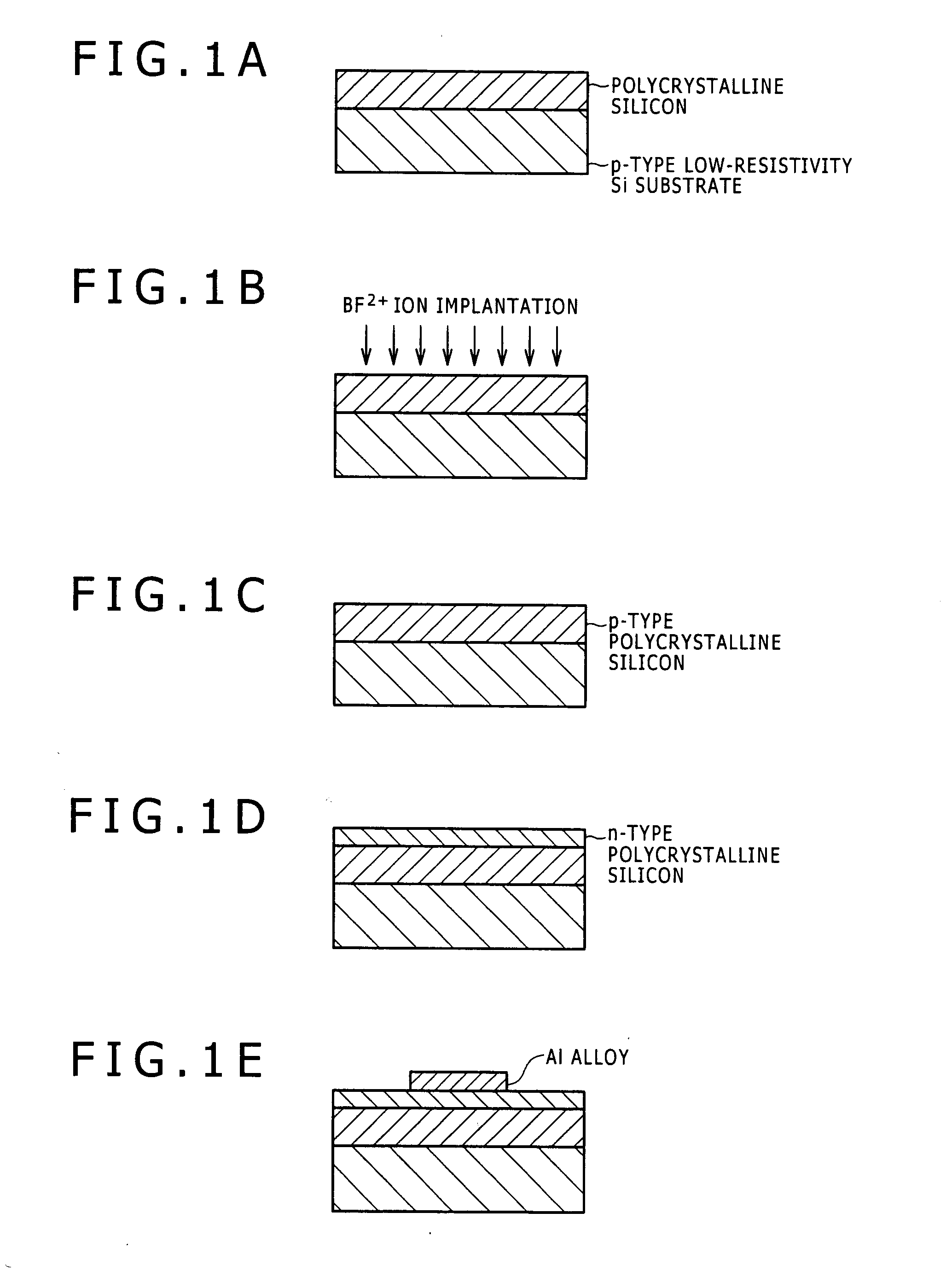
[0039]Evaluation elements (pn-junction elements) according to the examples of the invention and the comparative example were prepared. A process flow is shown in FIGS. 1A to 1E. A preparation method is described below.

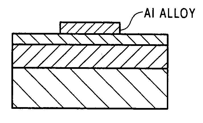
[0040]As shown in FIG. 1, first, a polycrystalline silicon film 200 nm in thickness was formed on a p-type low-resistivity silicon substrate by an LPCVD method (FIG. 1A). At that time, SiH4 was used for a source gas. Then, the film was subjected to ion implantation of BF2+ ions at a condition of 10 keV and 3×10¹⁵ / cm2 (FIG. 1B). Then, such an ion-implanted film was subjected to annealing at 800° C. for 30 min to be forme...

example 2

[0045]An Al alloy film 300 nm in thickness was deposited on a glass substrate by the sputtering method. Then, a resist pattern was formed by photolithography, and then the Al alloy film was etched with the resist as a mask to be formed into a stripe pattern shape 100 μm in width and 10 mm in length. A composition of the Al alloy film is the same as that shown in the column of source / drain electrode of Table 1. The etched Al alloy film was subjected to annealing at a temperature of 250 to 400° C. for 30 min. Then, the annealed Al alloy film was measured in electrical resistivity by the four-terminal method. A result is shown in a column of electrical resistivity of Table 1. Electrical resistivity of 1.3 times of electrical resistivity of a pure Al film (3.3 μΩ·cm) was used as a standard (3.3*1.3=4.3 μΩ·cm). Compared with the standard, small electrical resistivity was defined to be good, and large electrical resistivity was defined to be bad.

Evaluation of Results in Examples 1 to 2

[00...

example 3

[0051]Contact performance (contact resistance) when the Al alloy electrode and the transparent conductive film were directly connected to each other was investigated. Samples in which an ITO film was formed on various Al alloy electrodes as shown in Table 2 were formed at a condition of pressure of 3 mTorr and temperature of 200° C. under an Ar gas atmosphere. As the ITO film, a film of ITO including indium oxide added with tin oxide of 10 mass percent was used.

[0052]A Kelvin pattern having a contact hole in 10 μm square was prepared, and contact resistivity was measured by the four-terminal method using the Kelvin pattern. Contact resistivity of 2*10−4 Ωcm2 between a Cr thin film and ITO was used as a standard value, and resistivity not more than the standard value was defined to be good (◯), and resistivity more than the standard value was defined to be bad (x). An evaluation result is shown in Table 2.

[0053]When the Al alloy electrode includes Al—Si alloy, contact resistivity is ...


PUM


Abstract

Disclosed are a thin film transistor substrate where barrier metal can be omitted to be formed between a semiconductor layer of a thin film transistor and source and drain electrodes (barrier metal need not be formed between the semiconductor layer of the thin film transistor and the source and drain electrodes), and a display device. (1) A thin film transistor substrate has a semiconductor layer of a thin film transistor, a source electrode, a drain electrode, and a transparent conductive film, wherein the substrate has a structure in which the source and drain electrodes are directly connected to the semiconductor layer of the thin film transistor, and the source and drain electrodes include an Al alloy thin film containing Ni of 0.1 to 6.0 atomic percent, La of 0.1 to 1.0 atomic percent, and Si of 0.1 to 1.5 atomic percent. (2) A display device has the thin film transistor substrate.

Description

BACKGROUND OF THE INVENTION[0001]1. Field of the Invention[0002]The present invention belongs to a technical field in connection with a thin film transistor substrate and a display device.[0003]2. Description of Related Art[0004]In a display device of an active matrix type such as a liquid crystal display, thin film transistor (hereinafter, sometimes called TFT) is used as a switching element. A schematic diagram of a TFT element is shown in FIG. 2. The TFT element includes a gate electrode formed on a glass substrate, a non-doped semiconductor silicon layer provided via a gate insulating film, and impurity-doped semiconductor silicon layers contacted to the non-doped semiconductor silicon layer. Electrical connection with the respective impurity-doped semiconductor silicon layers is made using wiring metal including Al alloy. The wiring metal is referred to as a source electrode or a drain electrode. The drain electrode is further connected with a transparent conductive film used i...

Claims


Application Information

Patent Timeline
Patent Type & Authority Applications(United States)
IPC IPC(8): H01L33/00
CPCH01L29/78609H01L29/458G02F1/136227
Inventor KAWAKAMI, NOBUYUKIGOTOH, HIROSHIHINO, AYA
Owner KOBE STEEL LTD
Why Eureka
Try Eureka