Polymer electroyte membrane, membrane/electrode assembly and fuel cell using the assembly

a technology of electrolyte membrane and assembly, which is applied in the direction of cell components, electrochemical generators, cell component details, etc., can solve the problems of deterioration of electrolyte membrane, wall thickness loss, and molecular weight reduction

Inactive Publication Date: 2007-12-13
HITACHI LTD
View PDF4 Cites 23 Cited by
  • Summary
  • Abstract
  • Description
  • Claims
  • Application Information

AI Technical Summary

Benefits of technology

[0027]In accordance with the present invention, it is possible to

Problems solved by technology

Thus, it has been shown that the main cause for the deterioration of the electrolyte membrane is the wall thickness loss.
This leads to a decrease in molecular weight to cause dissolution, resulting in wall thickne

Method used


Image

  • Polymer electroyte membrane, membrane/electrode assembly and fuel cell using the assembly
  • Polymer electroyte membrane, membrane/electrode assembly and fuel cell using the assembly
  • Polymer electroyte membrane, membrane/electrode assembly and fuel cell using the assembly

Examples


example 1

(Manufacturing of Electrolyte Composite Membrane)

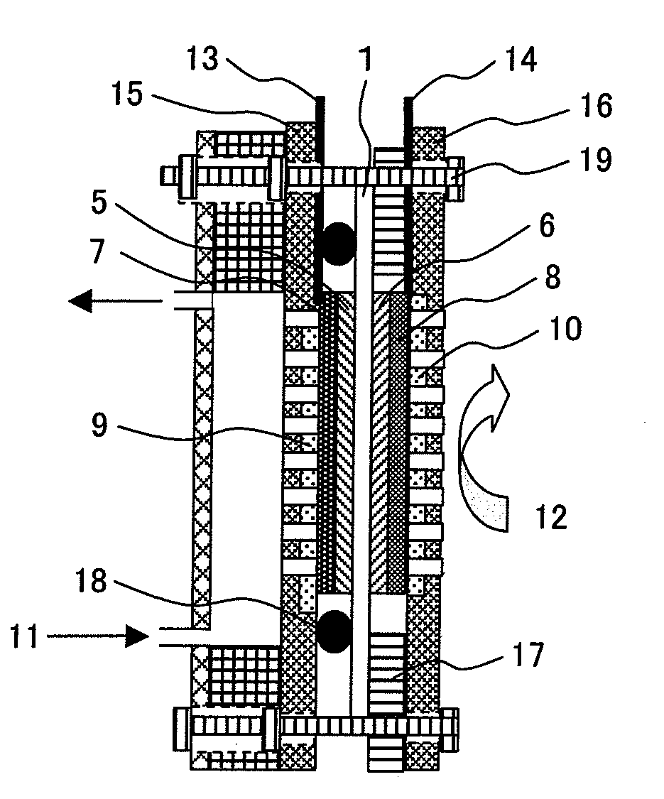
[0032]Sulfonated polyether sulfone (S-PES) with a number average molecular weight of 4×10⁴ and an ion exchange equivalent weight of 8×10² g / equivalent was dissolved in N,N-dimethylacetamide to manufacture a 30 wt % electrolyte solution. The electrolyte solution was cast and coated on a glass substrate. A polyolefin porous membrane was placed thereon, and impregnated therewith. Further, an electrolyte solution was cast and coated from thereabove. At this step, by controlling the amount of the electrolyte to be cast, the thicknesses of the electrolyte layers on the opposite sides of the polymer layer were changed. Thereafter, heating and drying were carried out at 80° C. for 20 minutes, and then at 120° C. for 20 minutes, thereby to remove the solvent in the solution. As a result, there was manufactured a solid polymer electrolyte composite membrane having a porous layer on the inner sides of a pair of electrolyte layers in which the th...

example 2

(Manufacturing of Electrolyte Composite Membrane)

[0034]Sulfonated polyether sulfone with a number average molecular weight of 4×10⁴, and an ion exchange equivalent weight of 11×102 g / equivalent was dissolved in N,N-dimethylacetamide to manufacture a 30 wt % electrolyte solution. The electrolyte solution was cast and coated on a glass substrate. A polyolefin porous membrane was placed thereon, and impregnated therewith. Further, the electrolyte solution formed in Example 1 was cast and coated from thereabove. Thereafter, heating and drying were carried out at 80° C. for 20 minutes, and then at 120° C. for 20 minutes, thereby to remove the solvent in the solution. As a result, there was manufactured a solid polymer electrolyte composite membrane having a porous layer on the inner sides of a pair of electrolyte layers in which the ion exchange equivalent weight of one electrolyte layer is larger than the ion exchange equivalent weight of the other electrolyte layer. The observation of ...

example 3

(Manufacturing of Electrolyte Composite Membrane)

[0036]Sulfonated polyether sulfone with a number average molecular weight of 7×10⁴ and an ion exchange equivalent weight of 8×10² g / equivalent was dissolved in N,N-dimethylacetamide to manufacture a 30 wt % electrolyte solution. The electrolyte solution was cast and coated on a glass substrate. A polyolefin porous membrane was placed thereon, and impregnated therewith. Further, the electrolyte solution formed in Example 1 was cast and coated from thereabove. Thereafter, heating and drying were carried out at 80° C. for 20 minutes, and then at 120° C. for 20 minutes, thereby to remove the solvent in the solution. As a result, there was manufactured a solid polymer electrolyte composite membrane having a porous layer on the inner sides of a pair of electrolyte layers in which the average molecular weight of one electrolyte layer is larger than the average molecular weight of the other electrolyte layer. The observation of the cross sect...


PUM


Abstract

Disclosed is an electrolyte membrane which is slowly degraded by a peroxide occurring at an air electrode catalyst layer, is low in cost, and is long in life, and a membrane electrode assembly. The electrolyte membrane has a first electrolyte layer which has an ion conductivity, a second electrolyte layer which has an ion conductivity, and, upon surface contact with methanol, is thicker than the first electrolyte layer, has a larger ion exchange equivalent, or a larger number average molecular weight, and a porous layer which has an ion conductive electrolyte impregnated therein, formed between the first electrode layer and the second electrode layer.

Description

CLAIM OF PRIORITY[0001]The present application claims priority from Japanese application serial No. 2006-159202, filed on Jun. 8, 2006, the content of which is hereby incorporated by reference into this application.FIELD OF THE INVENTION[0002]The present invention relates to a solid polymer electrolyte membrane, a membrane-electrode assembly (which is hereinafter abbreviated as a MEA), and a solid polymer type fuel cell (which is hereinafter abbreviated as a PEFC), and a direct methanol type fuel cell (which is hereinafter abbreviated as a DMFC).RELATED ART[0003]A fuel cell is expected as a future new energy because of its low pollution performance and high energy efficiency. The fuel cell electrochemically oxidizes a fuel such as hydrogen or methanol by oxygen, and thereby converts the chemical energy of the fuel into the electrical energy, and extracts it.[0004]The PEFC uses hydrogen as a fuel, operates at low temperatures, is high in output density, and can be reduced in size. Fo...

Claims


Application Information

Patent Timeline
IPC IPC(8): H01M8/10
CPCH01M8/1011H01M8/1027H01M8/1032Y02E60/523H01M8/106H01M2300/0094H01M8/1053Y02E60/50
Inventor ONUMA, ATSUHIKOHONBOU, HIDETOSHIKOBAYASHI, TOSHIYUKI
Owner HITACHI LTD
Why Eureka
Try Eureka