Optical Film

a technology of optical film and polarizing element, applied in the field of optical film, can solve the problems of phase separation, increased haze, and difficulty in simply controlling the wavelength dispersion property

Inactive Publication Date: 2007-12-27
SUMITOMO CHEM CO LTD
View PDF0 Cites 191 Cited by
  • Summary
  • Abstract
  • Description
  • Claims
  • Application Information

AI Technical Summary

Benefits of technology

[0006] The present invention has an object of providing an optical film which gives a desired retardation in a wider region even with a single optical film and additionally of which wavelength dispersion property can be arbitrarily controlled, a material suitable for this optical film, and a method for producing an optical film from this material.

Problems solved by technology

However, for changing the wavelength dispersion property, it is necessary not only to change the mixing ratio of the polymer A and the polymer B but also to change also the ratio of monomers used in a copolymer of the polymer A or the polymer B, and it is difficult to simply control the wavelength dispersion property, and additionally, a drawing process is also necessary for making a film.
In general, polymers reveal poor mutual compatibility, thus, when they are mixed, there occurs problems of phase separation and increase in haze when optically observed.
Recently, with increase in the size of FPD, it has been clarified that when the whole display image plane is observed from wide angles, a display image is colored (called coloring phenomenon) and white and black are inverted (called inversion phenomenon), and when visual angle is inclined toward reverse visual angle direction which is an upper direction of a display image plane, there occurs a problem of decrease in contract.

Method used


Image

  • Optical Film
  • Optical Film
  • Optical Film

Examples


example 1

Synthesis Example 1

Synthesis of Polymerizable Compound (1-1)

(Synthesis Examples of ethyl 4-(6-hydroxyhexyloxy)benzoate (a))

[0139] 150 g (0.90 mol) of ethyl 4-hydroxybenzoate, 186 g (1.35 mol) of potassium carbonate and 750 g of N,N-dimethylacetamide were weighed, and heated up to 80° C. Subsequently, 244 g (1.24 mol) of 6-bromohexanol was dropped over 2 hours, then, the mixture was stirred for 2 hours at 80° C. After cooling, the reaction liquid was poured into ice water, and extracted with ethyl acetate. The ethyl acetate phase was washed with water, then, the solvent was distilled off under reduced pressure to obtain 312 g of white solid containing ethyl 4-(6-hydroxyhexyloxy)benzoate (a) as the main component. As a result of analysis, (a) was obtained approximately quantitatively.

Synthesis Example of 4-(6-hydroxyhexyloxy)benzoic acid (b)

[0140] 312 g of white solid obtained above containing (a) as the main component was dissolved in methanol. Subsequently, a methanol solution ...

production example 1

of Optical Film

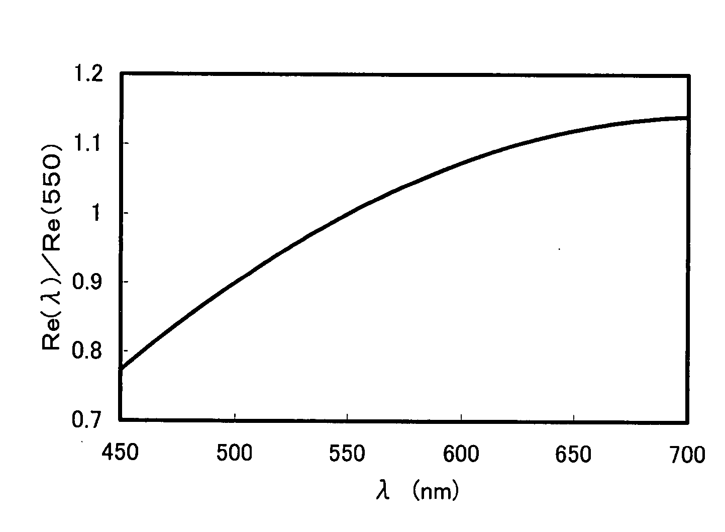
[0146] On a glass base plate, a polyimide alignment layer (SE-5291, manufactured by Nissan Chemical Industries, Ltd.) was applied, then, dried and annealed to obtain a membrane having a thickness of 138 nm. Subsequently, a rubbing treatment was performed, then, on the rubbing-treated surface, application liquid having a formulation in Table 5 was applied by a spin coat method, and dried for 1 minute at 55° C. The resultant un-polymerized film was observed by a polarization microscope to confirm mono-domain. Subsequently, irradiation with ultraviolet ray was carried out to obtain an optical film having a thickness of 1.5 μm.

TABLE 5Formulation of application liquidComponentwt %Polymerizable compound (1-1)10Rod-shaped polymerizable liquid crystal compound (3-3)10Photo-polymerizable initiator *12.5Leveling agent0.5Propylene glycol monomethyl ether acetate77

*1: Irgacure 907 (manufactured by Ciba Specialty Chemicals) (Measurement of wavelength dispersion property)

[0147] ...

example 2

Production Example 2 of Optical Film

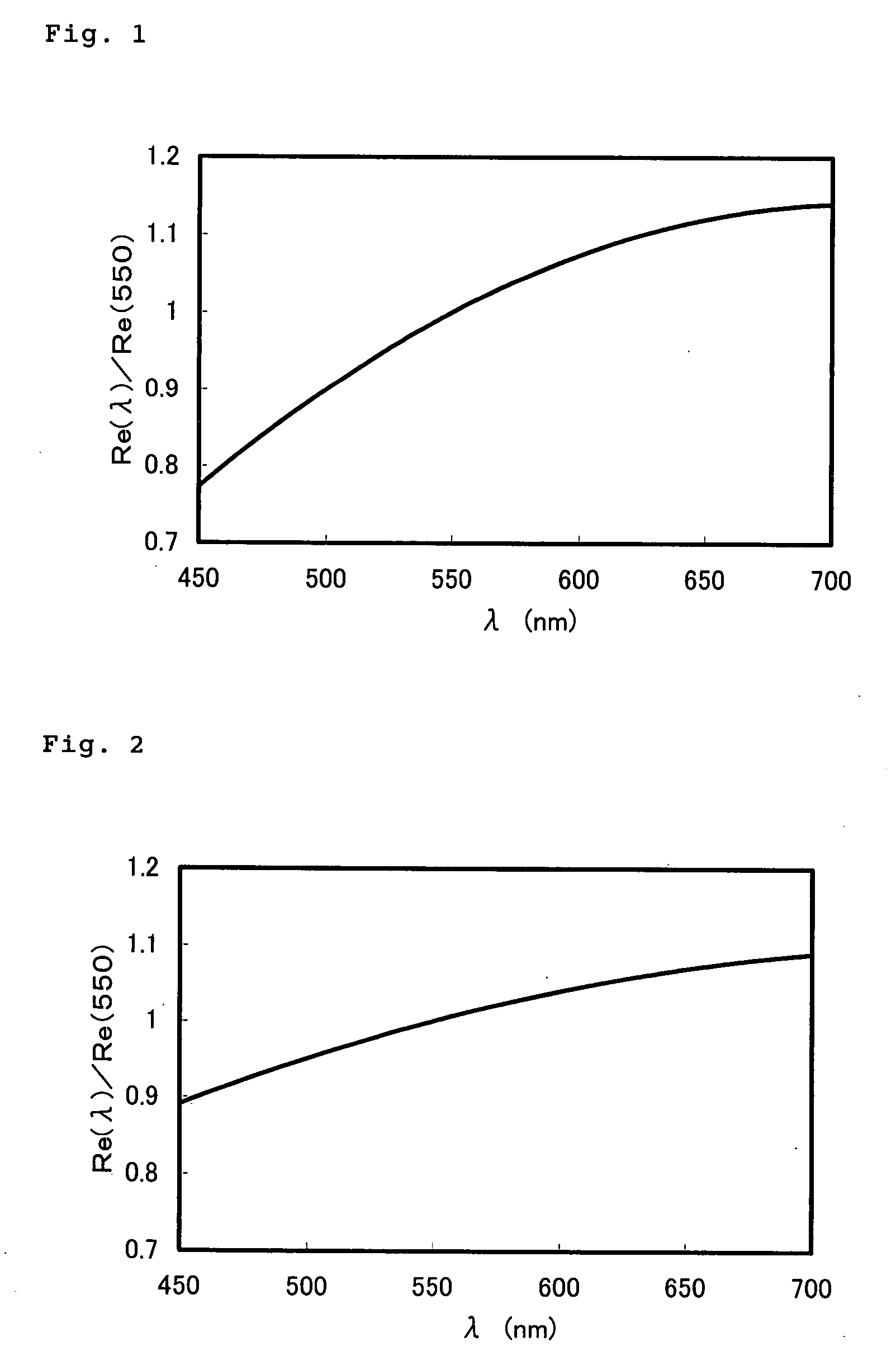
[0150] An optical film was produced in the same manner as in Example 1 (Production Example 1 of optical film) excepting the use of application liquid in Table 6.

[0151] The wavelength dispersion from 450 nm to 700 nm of the resulting optical film was measured in the same manner as in Example 1, and the result is shown in FIG. 2. [Re(450) / Re(550)] was 0.89 and [Re(650) / Re(550)) was 1.07.

TABLE 6Formulation of application liquidComponentwt %Polymerizable compound (1-1)6.67Rod-shaped polymerizable liquid crystal compound (3-3)13.33Photo-polymerizable initiator *12.5Leveling agent0.5Propylene glycol monomethyl ether acetate77

*1: Irgacure 907 (manufactured by Ciba Specialty Chemicals)


PUM

PropertyMeasurementUnit
thicknessaaaaaaaaaa
thicknessaaaaaaaaaa
wavelengthaaaaaaaaaa

Abstract

A composition comprising a polymerizable compound of the formula (1) and a rod-shaped polymerizable liquid crystal compound:
P2-E2-X2-B2-A2-(G2)t-Y-(G1)s-A1-B1-X1-E1-P1   (1)
(in the formula (1), Y represents a di-valent group, s and t represent each independently an integer of 0 or 1, G1 and G2 when s and t are 1 represent each independently —CR1R2—, R1 and R2 represent each independently an alkyl group having 1 to 4 carbon atoms, halogen atom or hydrogen atom, A1 and A2 represent each independently a di-valent cyclic hydrocarbon group, di-valent heterocyclic group, methylenephenylene group, oxyphenylene group or thiophenylene group, B1 and B2 represent each independently a di-valent group, X1 and X2 represent each independently a di-valent group, E1 and E2 represent each independently an alkylene group having 2 to 25 carbon atoms, and P1 and P2 represent a hydrogen atom or polymerizable group, at least one of P1 and P2 being a polymerizable group.).

Description

TECHNICAL FIELD [0001] The present invention relates to an optical film. BACKGROUND ART [0002] Flat panel displays (FPD) such as liquid crystal displays (LCD) and organic electroluminescences (EL) and the like showing space saving and low powder consumption as compared with CRT, are widely spread as image planes of computers, televisions, portable telephones, car navigations or portable information ends. In FPD, various optical films are used for reflection reduction, wide viewing angle and the like. As such optical films, there are mentioned, for example, reflection reducing films such as antireflection (AR) films and the like which lower the surface reflection coefficient by an optical interference effect by making a multilayer structure composed of optical thin membranes of different refractive indices; polarizing films allowing permeation only of lights of specific vibration directions and blocking other lights; retardation films optically compensating colors of interference col...

Claims


Application Information

Patent Timeline
Patent Type & Authority Applications(United States)
IPC IPC(8): C09K19/12C08G61/00C08G61/12C08G63/68C08G65/00C08G65/34C08G67/00C08G73/00C08G73/06C08G75/00
CPCC08F222/1006Y10T428/1036C09K19/3402C09K19/3444C09K19/3491C09K2019/0448C09K2019/3425G02B1/111G02F1/13363G02F2001/133633G02F2001/133637G02F2001/133638Y10T428/1005Y10T428/10C09K19/32C09K2323/00C09K2323/02C09K2323/03G02F1/133633G02F1/133637G02F1/133638C08F220/26C08J5/18G02B5/30
Inventor YAMAHARA, MOTOHIROHASEGAWA, HIKARU
Owner SUMITOMO CHEM CO LTD
Why Eureka
Try Eureka