Electroluminescent Wire

a technology of electroluminescent wire and wire, which is applied in the direction of discharge tube luminescnet screens, inorganic insulators, non-metal conductors, etc., can solve the problems of limited application in all perspectives, unstable, and short-lived final produ

Inactive Publication Date: 2008-02-14
ZHENG YAN
View PDF8 Cites 16 Cited by
  • Summary
  • Abstract
  • Description
  • Claims
  • Application Information

AI Technical Summary

Benefits of technology

[0024] In the present invention, the continuous base wire can be applied as bendable solid or hollow tube or wire made of plastic, rubber, or metal wire. The metal modified layer can be selected from a group consisting of gold, silver, copper, aluminum and stannum. The dielectric layer is a compound of dielectric powder and dielectric colloid evenly coating on the metal modified layer. The dielectric powder is selected from a group consisting of TiO2, BaTiO3, PbTiO3, and SrTiO3. The colloid is selected from a group consisting of epoxy resin, acrylic derivative, Cyanoethyl Sugar, Cyanoethyl Aethe, Cyanoethyl Cellulose that can be added with polyester, polyurethane, etc. The mixing ratio of the dielectric powder and the colloid is 1:1 to 1:2 by weight. A kind of coupling agent containing silicon or titanic is added into the dielectric layer, and the weight of the added coupling agent is about the 5% to 20% of the weight of the luminescent powder. Yttrium Aluminitum Garnel (YAG) is added into the luminescent powder, and the weight of the added YAG is about the 5% to 30% of the weight of the luminescent powder. The transparent conductive layer is made of ATO, which is a compound of the conductive nanometer metal oxide, containing one or more metal oxide of Sn, Sb, and Zn, and cement. The outer surface or the transparent conductive layer connects to the 1 to 4 outer protective conductive wires that are independent and evenly distributed. The protective conductive wire is made of metal wire having conductivity and flexibility, and can be coated with a metal modified layer made of anyone of the gold, silver, copper, aluminum, and stannum. The fluoroplastics is transparent, and enclosed by a plurality of transparent or translucent colorized plastic tubes. A continuous metal wire with hardness, ultra ultraviolet screening agent, and scattering agent or glass microballons are added in at least one layer of the plastic tubes respectively. The protective conductive wire can be coated with a well reflective layer, and can not rebound after bending. The protective conductive wires are enclosed by plastic tubes too. The colorized plastic tube also can be enclosed by a plastic enclosed tube made of transparent or translucent plastic. The shape of the plastic enclosed tube can be rectangular, circle, semicircle or a shape with a projecting frame.

Problems solved by technology

This greatly limits its application in all perspectives.
However, such method is not stable, and the final product is short-lived.
What is worse, the color purity is not well.
C) Due to the fact that PVC or PE is used as sealing material, the moisture-proof and durability function would not be guaranteed.
As a result, the moisture-proof green luminous material, having a longer life span have to be used thus causing the overall costs of the luminous wire unnecessarily increased and manufacturing procedure complicated.
D) Since the transparent conductive layer uses ITO making of In2O3 and its dopant, its cost would be rather expensive and susceptible under bad weather.
E) The weight and hardness of the base wire would limit the applications of such luminous wires.
For instances, the manufacturing process is still complex and the adhesion between the dielectric layer and the luminous layer is still weak.
That is to say, the improved procedure is still not suitable for mass production.
On the other hand, the life span of the improved luminous wires is not stable, and such product is still from independent usage.

Method used


Image

  • Electroluminescent Wire
  • Electroluminescent Wire
  • Electroluminescent Wire

Examples


Embodiment Construction

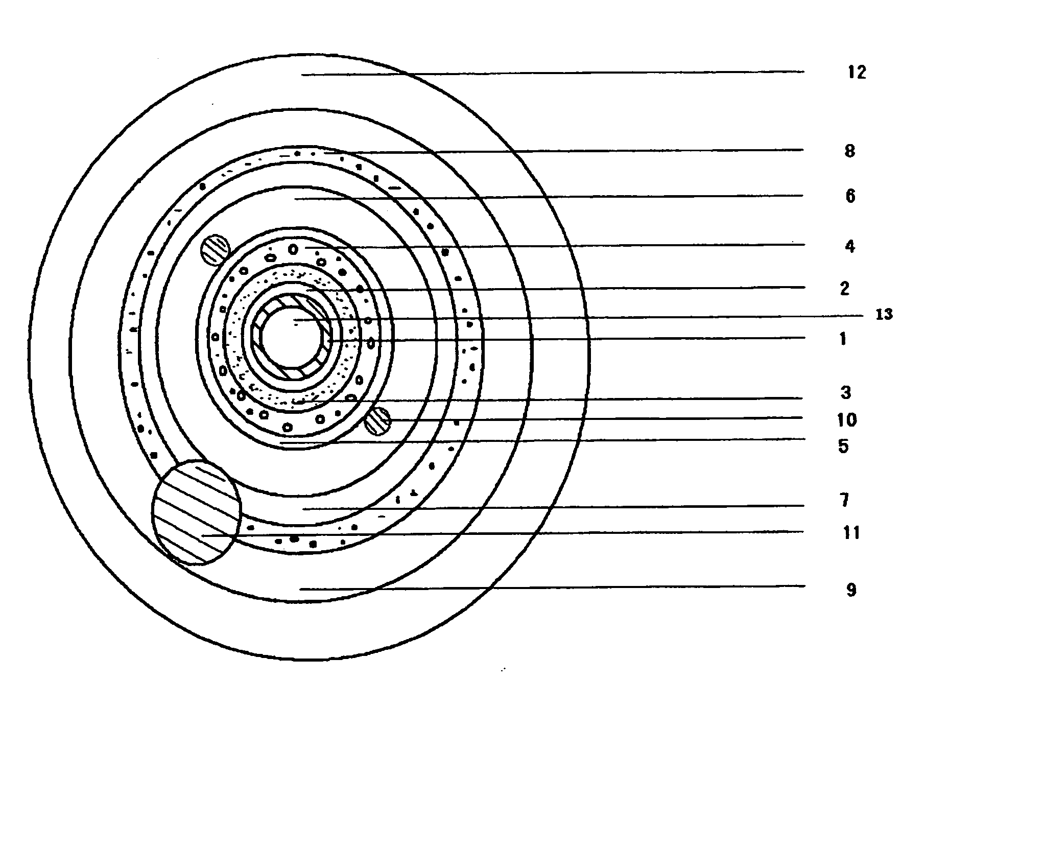
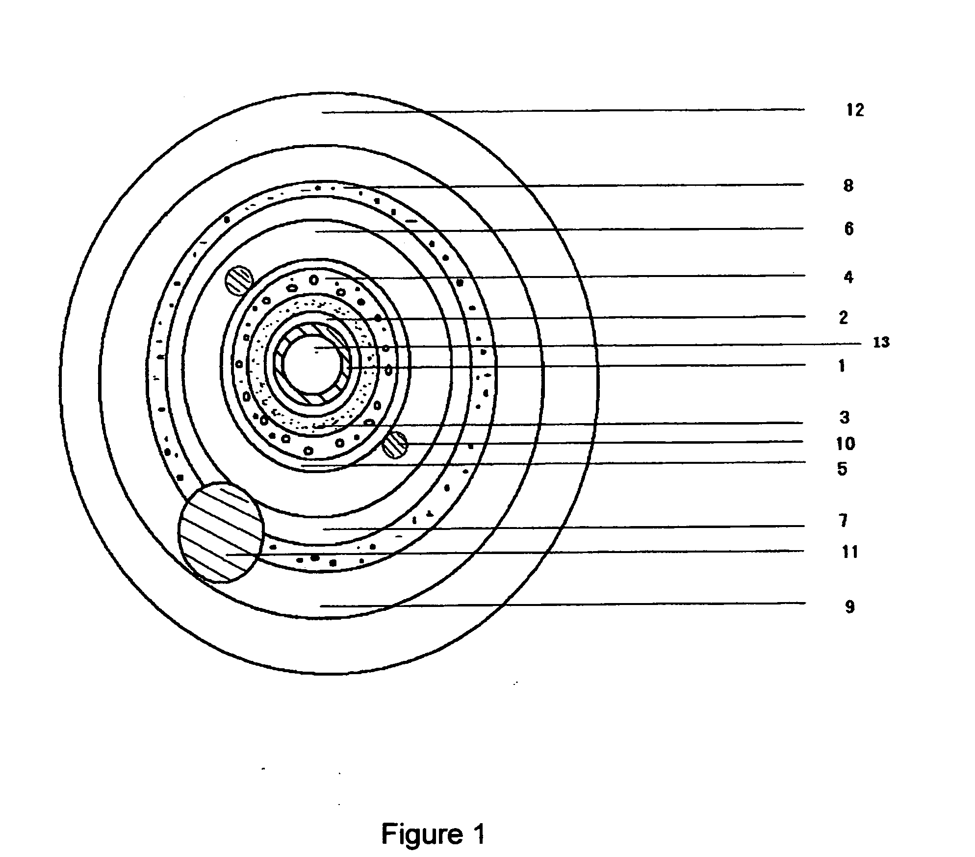
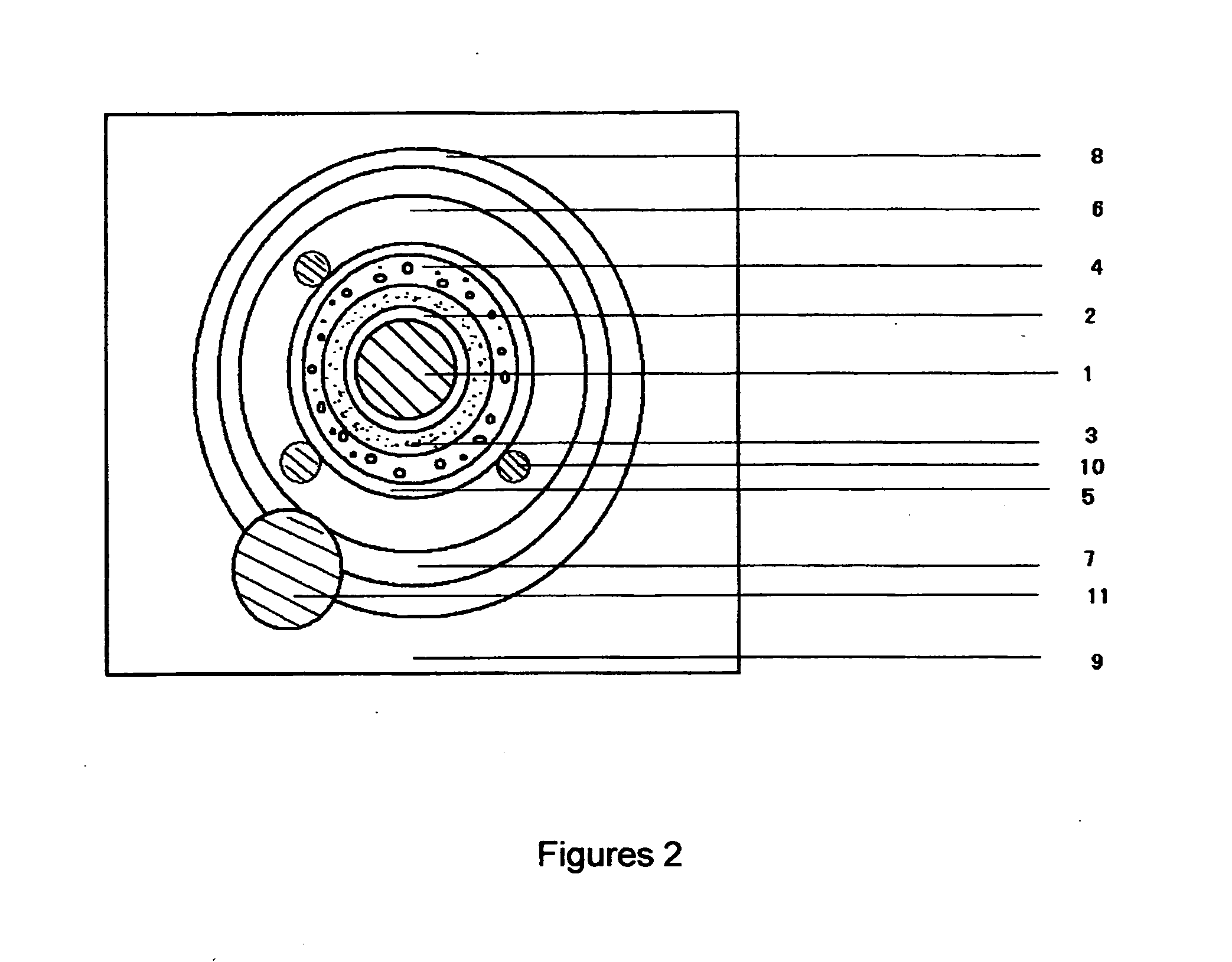
[0033] Referring to FIG. 1, the electroluminescent wire of the present invention comprises a continuous base wire 1, plated with a metal modified layer 2. The metal modified layer 2 is coated with a dielectric layer 3. The dielectric layer 3 is coated with a luminous layer 4 made of an electroluminescent material of one or more colors. The luminous layer 4 is coated with a transparent conductive layer 5, which is connected with 1 to 4 outer protective conductive wires 10. The outermost layer is sealed by a plurality of transparent or translucent plastic tubes 6-9, wherein the innermost layer 6 is prepared by fluoroplastics. It is noted that fluorescent dye or paint is added into at least one layer of the plastic tubes 7 to 9. A continuous metal wire 11 with a predetermined hardness is inserted into at least one layer among the plastic tubes 7 to 9, and the surface of the metal wire has a predetermined brightness that can increase the luminescent intensity by over 20%. The scattering...


PUM

PropertyMeasurementUnit
temperatureaaaaaaaaaa
diameteraaaaaaaaaa
diameteraaaaaaaaaa

Abstract

An electroluminescent wire includes a continuous base wire, plated with a metal modified layer. The metal wire is coated with a dielectric layer. The dielectric layer is coated with a luminous layer made of electroluminescent powder added with YAG to emit light. The luminous layer is coated with a transparent conductive layer. The surface of the conductive layer connects to 1 to 4 protective conductive wires, and all are enclosed by a fluoroplastics layer. The fluoroplastics layer is enclosed by a plurality of transparent and translucent colorized plastic tubes. Fluorescent dye or paint and scattering agent or glass microballons are added into at least one layer of the plastic tubes respectively. AC is applied between the metal modified layer and outer protective conductive wire.

Description

BACKGROUND OF THE PRESENT INVENTION [0001] 1. Field of Invention [0002] The present invention relates to a kind of luminous display device, and more particularly, relates to an electroluminescent wire which utilizes electric field for light emitting purposes. [0003] 2. Description of Related Arts [0004] Theoretically, an electroluminescent wire has the same luminous principle compared with the powder electroluminescent device, wherein the electroluminescent material is mainly the luminous material of II to VI groups. The luminous material will emit composite lights in the electric field. Furthermore, the luminous material consists of microcrystalline powder of 5 to 30 micron, in which a quantity of emitting line pairs existed so as to ensure the light emitting in the evenly distributed electric field. [0005] U.S. Pat. No. 5,485,355, U.S. Pat. No. 5,869,930, U.S. Pat. No. 6,400,093, EP0693803A, JP7-235375, CN ZL01250547.1, and CN ZL01251151.X respectively described the structure of t...

Claims


Application Information

Patent Timeline
Patent Type & Authority Applications(United States)
IPC IPC(8): H05B33/02B05D5/12
CPCC09K11/584C09K11/7774H01B1/02H01B1/08Y02B20/181H05B33/14H05B33/22H05B33/28H01B3/12Y02B20/00C09K11/7706
Inventor ZHENG, YAN
Owner ZHENG YAN
Why Eureka
Try Eureka