Microetching composition and method of using the same

a composition and micro-etching technology, applied in the field of micro-etching compositions, can solve the problems of fluctuation in the etching rate, copper discoloration, and insufficient direct bonding strength of copper and resin layers, and achieve the effect of improving the bonding strength

Active Publication Date: 2008-02-21
MACDERMID ACUMEN INC
View PDF15 Cites 10 Cited by
  • Summary
  • Abstract
  • Description
  • Claims
  • Application Information

AI Technical Summary

Benefits of technology

[0014] The present invention is directed to an improved microetching composition and a method of using the same to provide surface roughness to copper and copper alloy surfaces, in order to improve the bonding strength between the copper or copper alloy surface and a resin composition applied thereon.

Problems solved by technology

However, direct bonding of copper and resin layers does not always provide sufficient bonding strength.
However, these compositions can be unstable due to decomposition of the hydrogen peroxide, which results in fluctuations in the etching rate, discoloration of metals other than copper, and other problems.
However, these etching solutions can etch the copper surfaces more deeply than is desired.
Lastly, low metal etch depths reduce the rate at which metal builds up in the adhesion promoting composition.

Method used


Image

  • Microetching composition and method of using the same
  • Microetching composition and method of using the same

Examples


example 1

[0046] Acetonitrile was tested as an additive in a conventional copper chloride / sodium chloride microetching system. The modified system had the following composition:

Copper chloride43 g / lSodium chloride48 g / lAcetonitrile200 g / l 

Hydrochloric acid to a pH of 1.0

[0047] The solution did not produce any better results than the conventional solution until a higher concentration of acetonitrile was used. At 200 ml / l of acetonitrile, a matte and brown surface was obtained with an etching depth of 170 microinches.

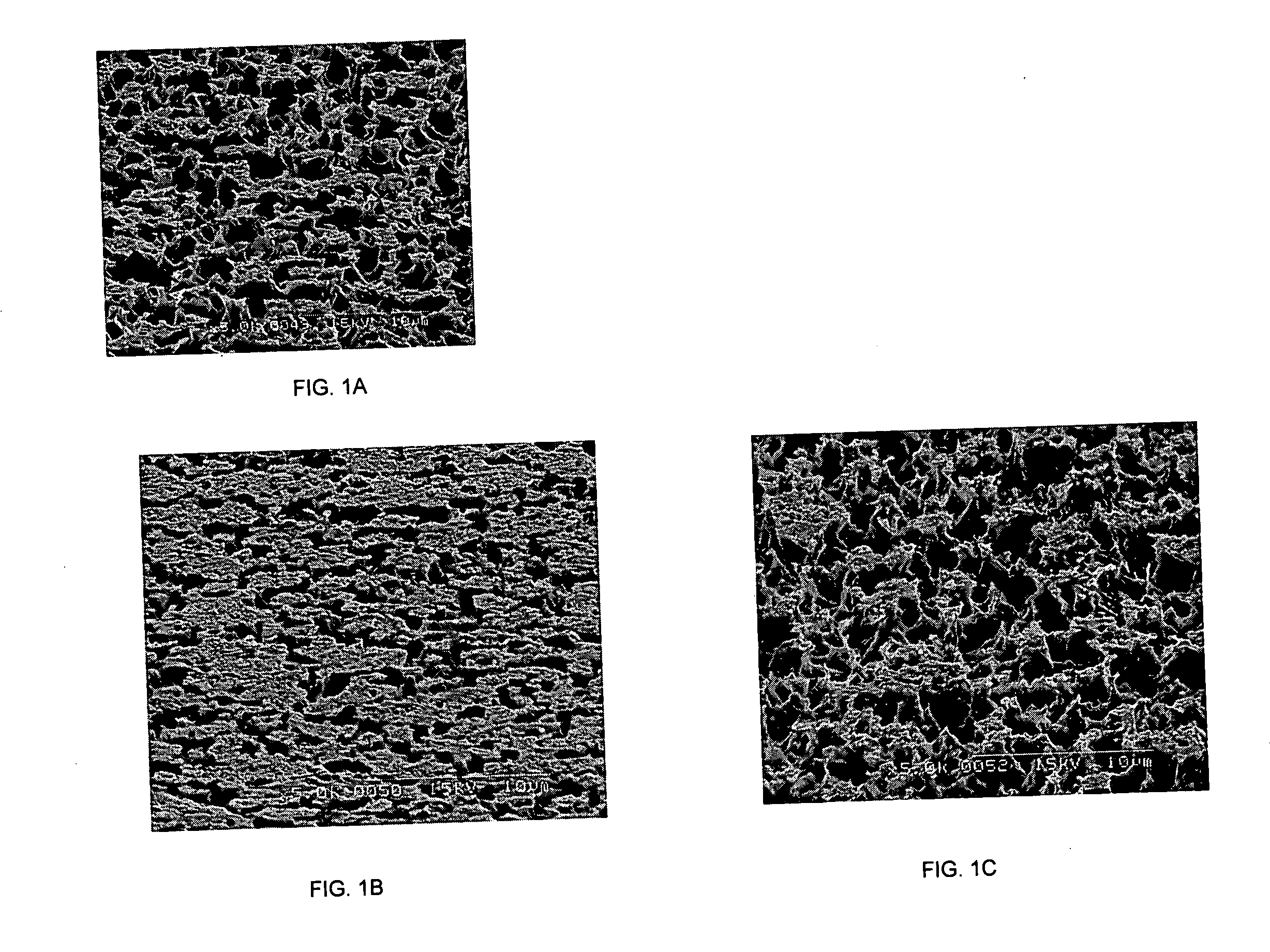
[0048] In order to reduce the etching depth, the concentration of copper chloride was reduced to 15 g / l from 43 g / l and no sodium chloride was added. The etching depth was thus reduced to about 59 microinches. A scanning electron microscope (SEM) image of the surface is provided in FIG. 1A.

[0049] Copper was then loaded at 5.3 g / l in order to artificially age the solution. Sodium chloride was added to control the etching rate and hydrochloric acid was added to control pH. An et...

example 2

[0051] The effectiveness of adiponitrile in a copper chloride / sodium chloride microetching system was also tested in accordance with the invention, and the following solution was prepared:

Copper chloride74 ml / l (43 g / l)NaCl48 g / lAdiponitrile 2 ml / l

Hydrochloric acid to a pH of 1.0

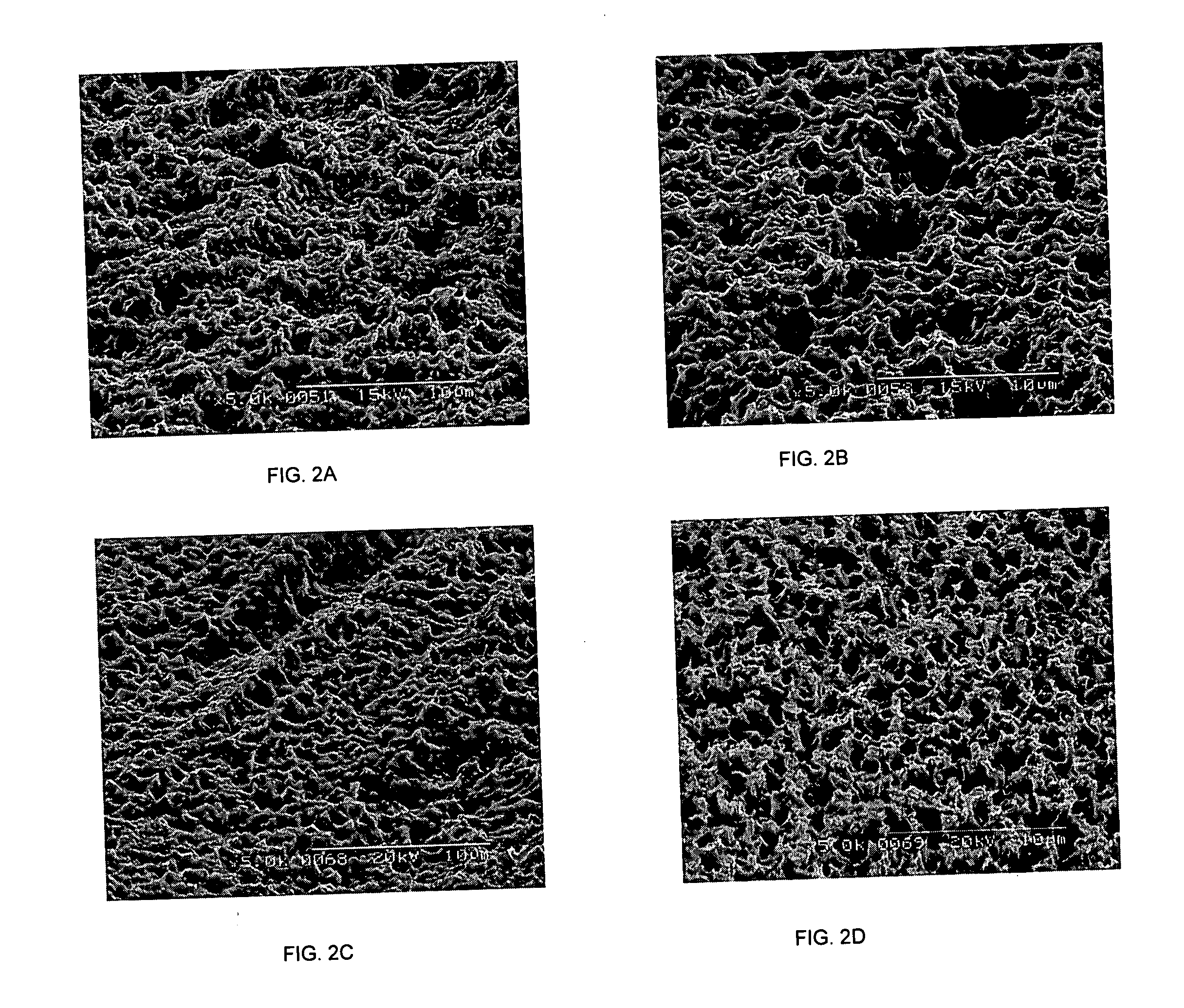
[0052] An etching depth of about 60 microinches was obtained and a SEM image of the surface is provided in FIG. 2A.

[0053] When P-400 (polyethylenimine, Mn-423) (available from Aldrich Chemical Company) was added to the composition, an etching depth of about 65 microinches was obtained. A SEM image of the surface is provided in FIG. 2B.

[0054] It was observed that solids formed in the solution after loading copper and a layer of yellow solid was present on the copper surface.

[0055] Butyl carbitol was used to dissolve the solid, and the following solution was prepared:

Copper chloride 74 ml / lNH4Cl 44 g / lButyl carbitol200 ml / lAdiponitrile 2 ml / l

[0056] An initial etch depth of 81 microinches was obtained, ...


PUM

PropertyMeasurementUnit
concentrationaaaaaaaaaa

Abstract

The present invention is directed to a microetching composition comprising a source of cupric ions, acid, a nitrile compound, and a source of halide ions. Other additive, including organic solvents, a source of molybdenum ions, amines, polyamines, and acrylamides may also be included in the composition of the invention. The present invention is also directed to a method of microetching copper or copper alloy surfaces to increase the adhesion of the copper surface to a polymeric material, comprising the steps of contacting a copper or copper alloy surface with the composition of the invention, and thereafter bonding the polymeric material to the copper or copper alloy surface.

Description

CROSS REFERENCE TO RELATED APPLICATION [0001] This application is a continuation-in-part of application Ser. No. 11 / 316,010 filed Dec. 21, 2005.FIELD OF THE INVENTION [0002] The present invention relates to microetching compositions useful for treating metal surfaces, such as copper and copper alloy surfaces, in the manufacture of printed circuit boards. BACKGROUND OF THE INVENTION [0003] Printed circuits containing one or more circuitry innerlayers are in prominent use today as demand increases for further and further weight and space conservation in electronic devices. [0004] Successful fabricating of multi-layer printed circuit boards requires bonding together of copper and resin layers. However, direct bonding of copper and resin layers does not always provide sufficient bonding strength. It is therefore common to improve copper-resin bonding strength by providing surface roughness to the copper surface, whereby mechanical bonding between the copper and the resin layers can be e...

Claims


Application Information

Patent Timeline
Patent Type & Authority Applications(United States)
IPC IPC(8): C23F1/16C09K13/04C09K13/06
CPCC23F1/18H05K2203/122H05K3/383
Inventor FENG, KESHENGKAPADIA, NILESHCASTALDI, STEVEN A.
Owner MACDERMID ACUMEN INC
Why Eureka
Try Eureka