
End-Block for a Rotatable Target Sputtering Apparatus

a sputtering apparatus and end block technology, applied in the field of sputtering apparatus, can solve the problems of new problems, dc supply problems, and serious drawbacks, and achieve the effect of reducing noise and low electrical nois

Inactive Publication Date: 2008-04-17
SOLERAS ADVANCED COATINGS NV
View PDF9 Cites 10 Cited by
  • Summary
  • Abstract
  • Description
  • Claims
  • Application Information

AI Technical Summary

Benefits of technology

[0013] It is therefore an object of the current invention to raise the throughput of large area coating installations by enabling higher power levels to be supplied to the targets. Another object of the present invention targets the reduction of the joule heating of the rotatable electrical contact inside the end-block. An advantage of the present invention is that it reduces the root cause of the joule heating—namely the magnitude of the skin effect—rather than countering the symptoms—i.e. the increased temperature—by having an improved cooling as in the prior art solutions. A further object of the invention is to provide an end-block with a rotatable electrical contact that is less prone to wear, more specifically groove formation.
[0014] According a first aspect of the invention an end-block for energising a rotatable target is provided. End-blocks are known in the art. They serve to rotatably hold the target tube, to make it turn and to electrically feed the target tube whilst feeding and evacuating a cooling liquid to it. Over and above the end-block must maintain vacuum integrity as the plasma processes normally take place at low pressures. Two target support configurations are currently in use: one where both ends of the tube are held by an end-block such as e.g. disclosed in U.S. Pat. No. 5,096,562 and one system wherein the target tube is held at one end only such as e.g. disclosed in U.S. Pat. No. 5,200,049. In the latter case a single end-block provides all the necessary functionalities (support, rotation, electricity, vacuum integrity and coolant). In the former case, different functionalities can be allocated to different end-blocks: e.g. the first end-block provides coolant and electrically energises the target, while the second drives the target rotation. The invention concerns the end-block that provides for the rotatable electrical connection between the power source and the rotatable target in either of the two target support configurations.
[0015] Such an end-block with a rotatable connection comprises a socket and a spindle coaxially mounted inside the socket. The spindle and socket can rotate relative to one another by means of ball bearings or sliding bearings or any other means known in the art. The socket comprises at least one electrical contact ring that connects to a first electrical end. Such a contact ring is made of an electrically conductive material that is sufficiently resistant to slide wear. The materials used most to this end are copper or brass or bronze.
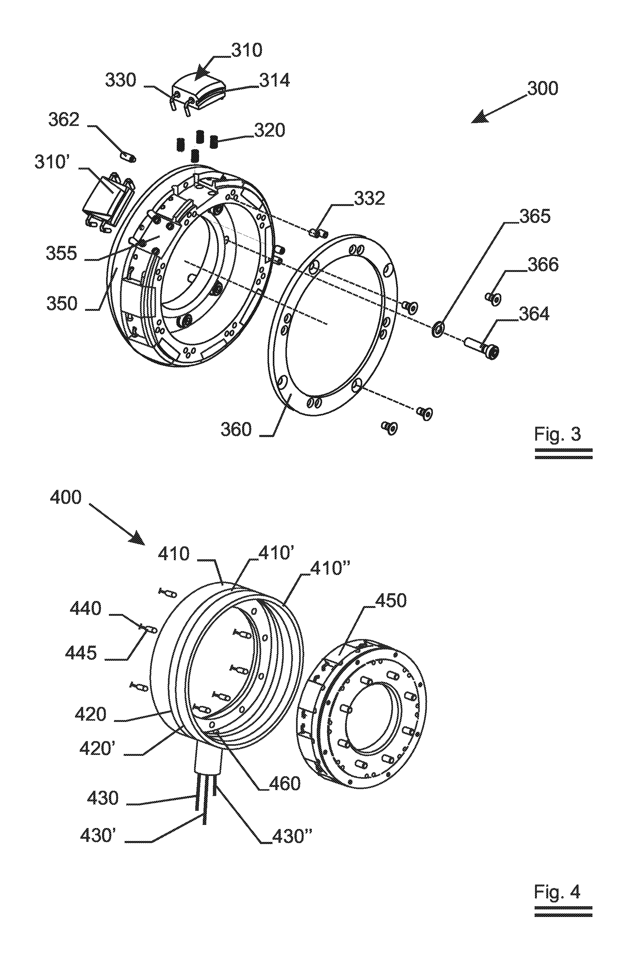
[0016] The inventive end-block (independent claim 1) is characterised by the features that the spindle comprises a series of electrically conducting shoes i.e. the shoes move with the spindle that is situated inside the socket. Such shoes are also called brushes. In order to balance the mechanical forces on the spindle, the shoes must be mounted evenly distributed on the circumference of the spindle. So at least two of these shoes must be present to equalise the radial forces on the spindle. The shoes are in electrical and mechanical sliding contact with the inner surface of the socket ring or rings. In order to ensure this contact at all times, each and every one of these shoes is pressed individually by a resilient element in the radially outward direction i.e. against the inner surface of the ring or rings. All the shoes are electrically connected to a second electrical end namely the spindle.
[0017] Although two shoes suffice to make the invention work, it is more preferable to use an integer number of shoes from 4 to 16 to ensure a connection with low electrical noise (dependent claim 2). With a lower number of shoes, the noise will not average out very well. With 17 or more shoes the reduction in noise is insignificant.
[0018] Between the shoes, there is a gap sufficiently wide that the shoes can move independently from one another. The gaps are such that they allow the ring to cool down after passage of the shoe. It is preferred that less than 70% of the circumference of the inner ring or rings of the socket is covered by the shoes. More specifically it is meant that the sum of the arc lengths spanned by the shoes is less than 0.70 times the circumference of the inner ring or rings of the socket. It is even more preferred that the shoes cover less than 50% of the circumference of the spindle. The contact between the shoes and the ring or rings must occur in a substantially dry environment (i.e. not in a liquid) in order to allow the formation of a conducting patina on the ring or rings.

Problems solved by technology

While in the first rotating target installations (see U.S. Pat. No. 4,356,073) the electric supply to the target was a direct current, it became soon apparent that this DC supply had some serious drawbacks when depositing materials in a reactive atmosphere: dielectric reaction products tended to cover—to ‘poison’—the target and the positively biased vacuum installation walls—acting as an anode—and impede further sputtering.
Due to the dielectric formed on the target, ‘arcing’ became a major problem.
While AC sputtering allowed for a further increase in power supplied to the target, it also led to new problems.
Although the above prior-art may alleviate the consequences of the joule heating, they do not reduce the root cause of the problem, namely the restriction of the current carrying area due to the skin effect.

Method used


Image

  • End-Block for a Rotatable Target Sputtering Apparatus
  • End-Block for a Rotatable Target Sputtering Apparatus
  • End-Block for a Rotatable Target Sputtering Apparatus

Examples


Embodiment Construction

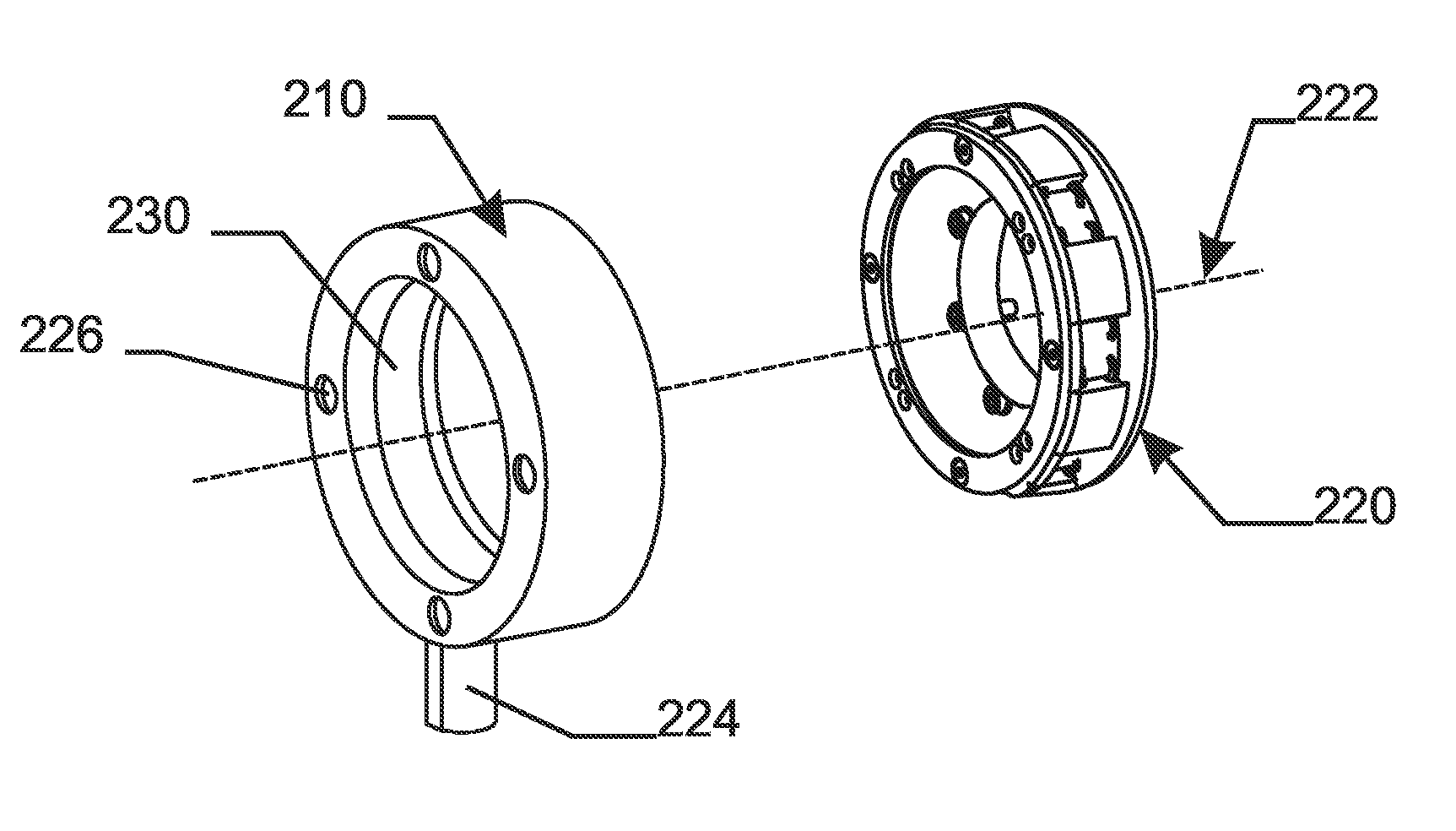
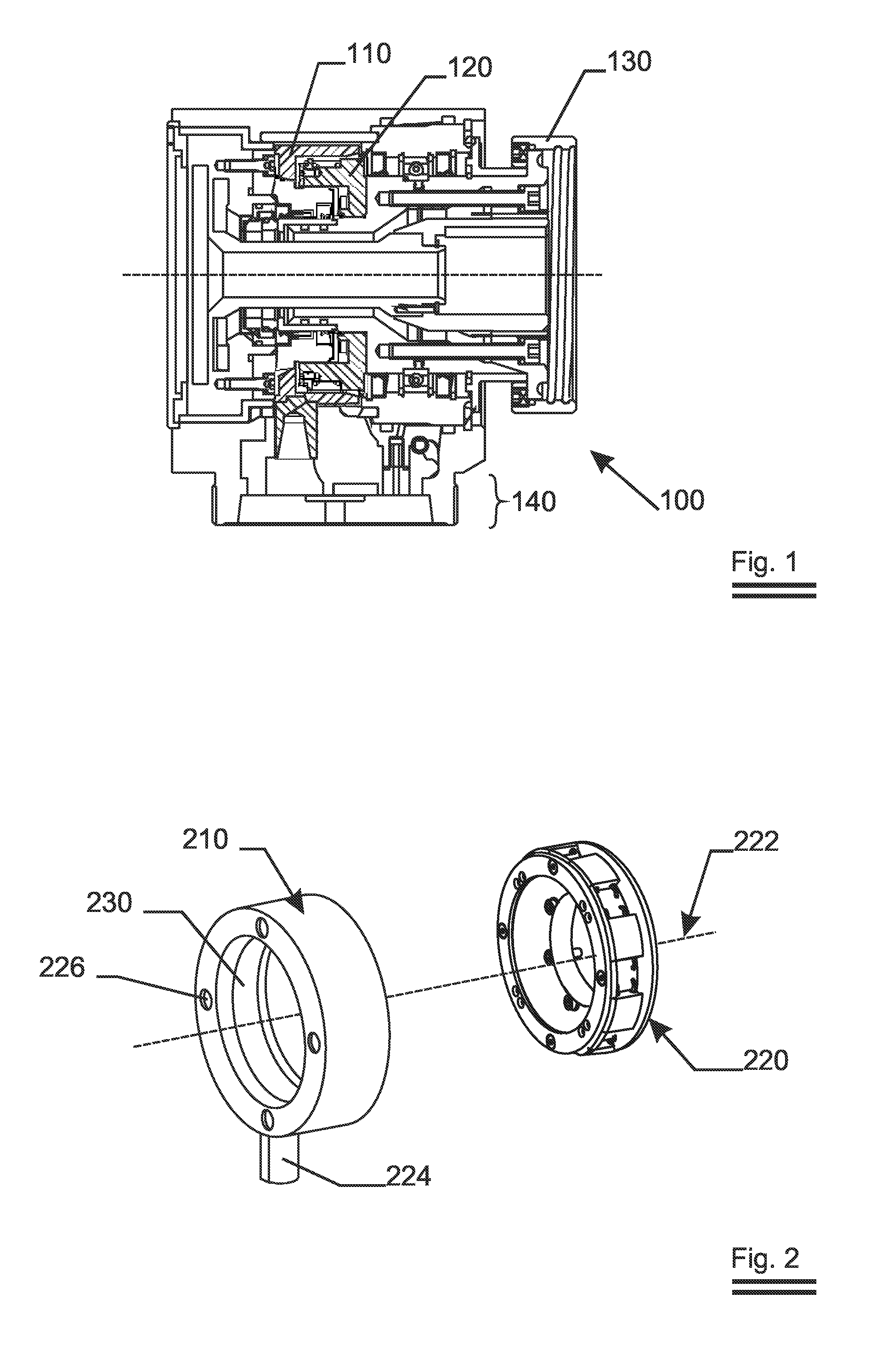
[0038] The invention concerns an end-block of which FIG. 1 shows an actual cross section 100. This particular end-block combines the functionalities of rotatably carrying one end of the tube, feeding and collecting coolant—usually water—to and from the target and transferring electrical current to the target. As the invention primarily concerns the latter functionality, the implementation of the other functionalities will not be discussed in detail since they are not crucial to understand the gist of the invention. The target (not shown) is inserted into and held by the clamping ring 130. The end-block 100 is held by a quick release coupling (not shown) that engages the holding section 140 to the sputtering apparatus (not shown). The socket 110 receives the spindle 120, the latter being rotatable with respect to the former.

[0039]FIG. 2 shows an isometric view in which the cylindrical socket 210 and the spindle 220 are shown separated from one another. Both parts share the same rota...


PUM

PropertyMeasurementUnit
Electrical conductoraaaaaaaaaa
Resilienceaaaaaaaaaa

Abstract

An end-block for electrically energising a rotatable tubular target in a vacuum coating installation is disclosed. The end-block has a rotary electrical contact that reduces the joule heating effects when operating in alternating current mode. When compared to known end-blocks, this is achieved by increasing the number of contact areas between a contacting ring and a series of circumferentially mounted contacting shoes. Also the contact shoes are being pressed radially outwardly by means of resilient elements against the contacting ring.

Description

FIELD OF THE INVENTION [0001] The invention relates to the technical field of sputtering apparatus with a rotating tubular sputtering target that are commonly used now for the deposition of thin films. More specifically the invention relates to the end-blocks that amongst others transfer electrical power to the rotating sputtering target. BACKGROUND OF THE INVENTION [0002] Large area, vacuum deposition equipment using tubular rotating targets has become the predominant method to deposit thin films on large area substrates such as e.g. window glass. In these installations, material is sputtered away from the rotating target by means of a plasma. The throughput through these huge installations determines their economic profitability. This throughput is—next to other factors such as uptime—determined by the physical deposition speed of material on the substrate. On its turn, this deposition speed depends on a number of factors such as the material that is to be deposited, the line spee...

Claims


Application Information

Patent Timeline
IPC IPC(8): H01J37/34
CPCH01J37/3435H01J37/3405
Inventor DELLAERT, KRISTDE BOSSCHER, WILMERTDE BOEVER, JOANNESPORTEMAN, STIJN
Owner SOLERAS ADVANCED COATINGS NV
Learn More