Electroporation devices and methods of using same for electroporation of cells in mammals

a technology of electroporation device and electroporation method, which is applied in the field of electroporation device and method of using same for cell electroporation in mammals, can solve the problems of limited scope of vivo plasmid transfer technology, effective entry of antigens,

Active Publication Date: 2008-04-17
INOVIO PHARMA
View PDF24 Cites 225 Cited by
  • Summary
  • Abstract
  • Description
  • Claims
  • Application Information

AI Technical Summary

Problems solved by technology

However, the barrier posed by the stratum corneum layer (1.1.1) of the epidermis (1.1) (see FIG. 1) tends to prevent effective entrance of antigens into the epidermis.
In vivo plasmid transfer technology, particularly as it relates to the transfer of plasmids to intradermic (“ID”) or subcutaneous (“SQ”) tissue or cells, has traditionally been limited in scope because in vivo expression levels resulting from the naked DNA (plasmid) transfer have been low, with only fractions of those achieved by viral gene transfer.
Consequently, direct injection of plasmid DNA has become a desired delivery technique, however, efficient delivery into cells and protein expression levels have been a challenge.
One of the challenges of skin EP in large mammals and humans is the individual variation of skin thickness, as well as variation in skin thickness between different anatomical regions.
However, the use of EP in living organisms has several problems, including cell death that results from generated heat and the inability of electropores to reseal.
The beneficial effects of the drug or biomolecule are extremely limited in EP methods where excessive cell heating and cell death occurs.
Certainly, the difference in upper limit amplitudes of a voltage pulse between electroporation protocols that facilitate effective electroporation and electroporation protocols that cause the cells to die are very small.
Thus, the overheating of cells between across electrodes serves as a principal cause for the ineffectiveness of any given electroporation voltage pulsing protocol.
A certain minimum voltage must be present to generate a current, but the quantity of ions deposited cannot be determined from a pre-determined voltage.
The effectiveness of electroporation is limited by the fact that there is a threshold value for the pulse intensity below which electroporation does not occur, and an upper limit above which the cells are destroyed.
Experimental evidence shows that the difference between the upper and lower limits is so small that it is very difficult to design effective pulsing protocols without undue experimentation.
This makes use of the technique difficult, mostly when one targets tissues that inherently have a non-homogeneous cell composition, such as skin—cells in epidermis and dermis of different thickness and number of strata, fat, fascia, blood vessels of different dimensions from capillaries to small vessels; only a true software driven device capable of instantaneously analyzing the instant conditions variable from individual to individual and between locations on the skin surface of each individual and adapting the output to the specific conditions would fulfill these requirements.
However, the existing commercial electroporation devices do not have the firmware designed to enable measurement of the exact amount of current to which the cells are exposed.
The unregulated current generated with conventional electroporation devices may generate amounts of heat in tissues that can easily kill cells.
The difficulties present in many electrodes stem from the fact that the pulse energy is concentrated in the center of the array, the point where the material to be transfected is deposited.
As a result, the spatial distribution of energy delivery assumes a very non-uniform character.
Also, commercially existing electrodes for large animal applications and humans generally do not allow for ID or SQ targeting of dendritic cells, as they are typically too long, of an inappropriate gauge and improper bevel orientation.
Furthermore, commercially available electroporation devices and needle arrays typically do not permit for control of inter and intra-individual variation of tissue resistance, thickness and local conditions.
In addition, electroporation devices which use skin and muscle invasive replaceable needle arrays as electrodes to deliver the electric current require maintenance of sterile conditions when the needle array replacement occurs.

Method used


Image

  • Electroporation devices and methods of using same for electroporation of cells in mammals
  • Electroporation devices and methods of using same for electroporation of cells in mammals
  • Electroporation devices and methods of using same for electroporation of cells in mammals

Examples


example 1

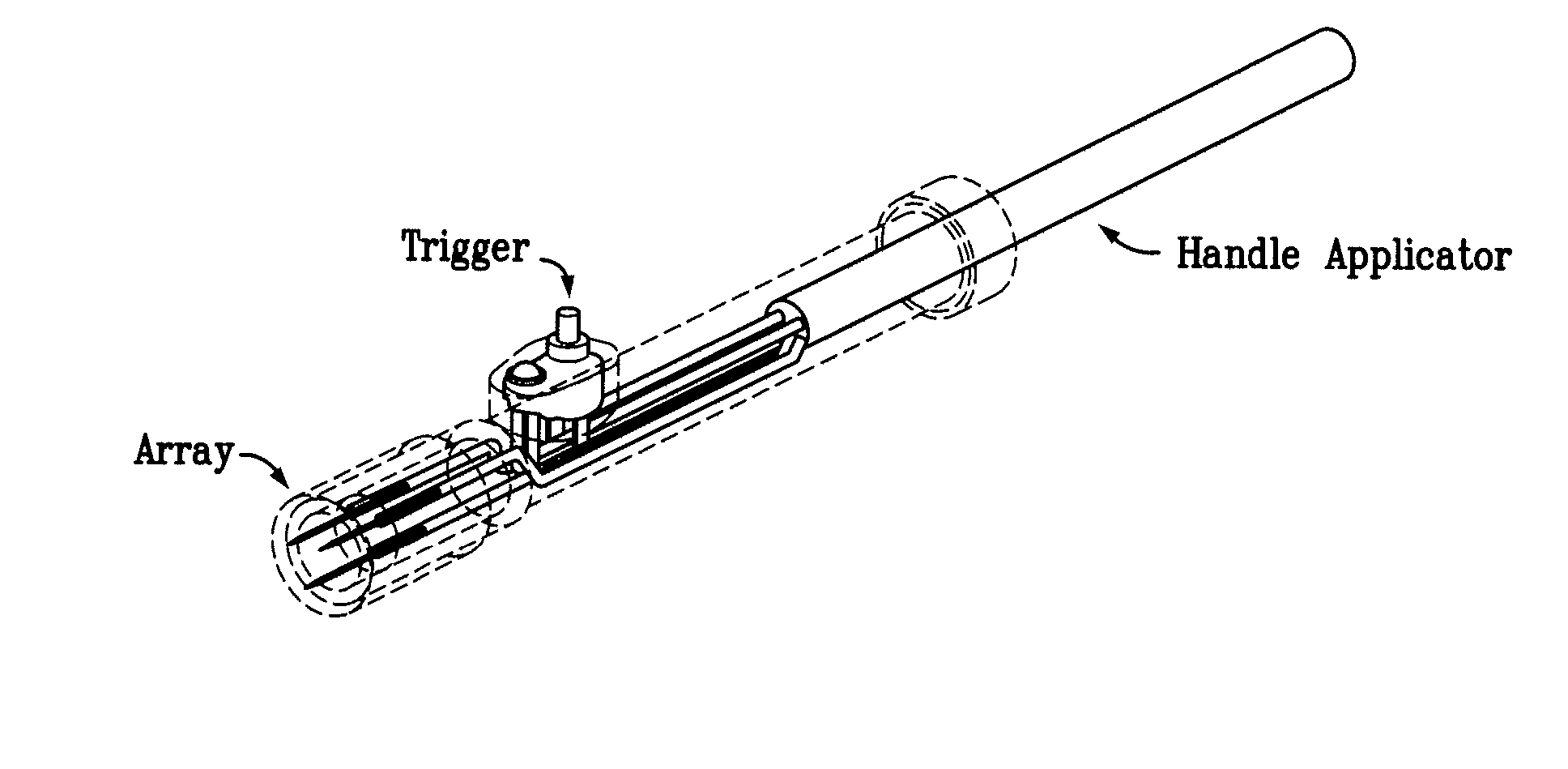
Operation of the Electro-Kinetic Device (“Skin EP Device”) for Skin Electroporation

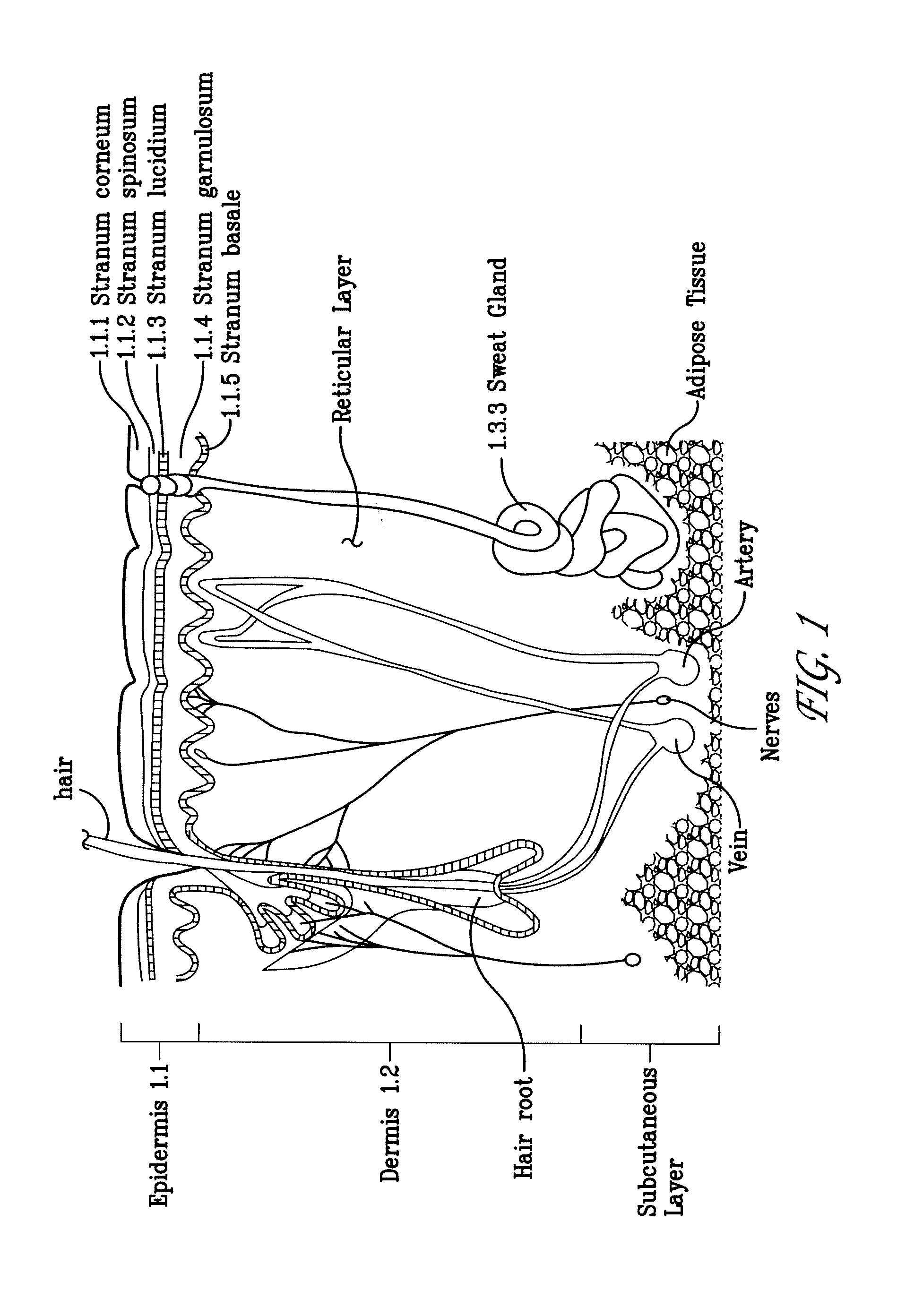
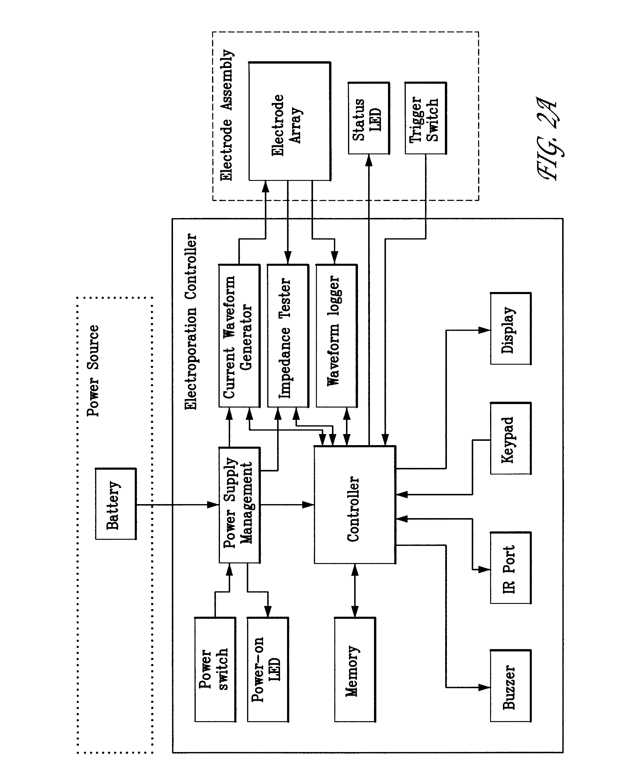
[0132] First, the power to the skin EP device is turned on. The firmware remains in the idle state until input is received from the user. To start an electroporation sequence, a password is entered to obtain an introductory prompt on the LCD. At this point, the handle assembly activator switch is pressed. The user then enters a number, preferably a subject identification number, which is logged with the data of every pulse stored for later download. The number is preferably entered using a numeric keypad. The biomolecule formulation is than administered as an ID or SQ injection in a reasonably small injection volume, ideally 25-200 skin liters and the skin electrode array is inserted into the skin to completely surround the injection area which is easily visualized. The user is then prompted, via a “beep” from the buzzer, to press the activation switch to continue the electroporation sequence. After ...

example 2

Data Acquisition and Storage

[0137] The skin EP device software or firmware enables real time data acquisition and storage in non-volatile memory. FIG. 2C illustrates a first portion of data that may be collected during the electroporation process. The first section of the file header contains the file name (“2.1”) and the animal number (“2.2”). The columnar data (“2.3”) describes the pulse in sequence, the wait time before pulsing, the pulse width, and the pulse current for each of the three electrodes. FIG. 2.4 illustrates a second portion of data, which identifies the configuration of each electrode during a given pulse sequence. FIG. 2.5 illustrates a formatted version of a third portion of raw data for the same electroporation. The file is downloaded from the skin EP device as a Microsoft Excel CSV file. The data are copied and pasted into a template Microsoft Excel Spreadsheet file. Columns in the spreadsheet represent measured voltage (V) and current (Amps) during the electro...

example 3

Plasmid Design, Delivery Methods, and Experimental Study in Pigs

[0138] Plasmid construction. pEGFP-N1 (Clontech, Mountain View, Calif.) used in the experiments described herein, encodes a red-shifted variant of wild-type GFP which has been optimized for brighter fluorescence and higher expression in mammalian cells (excitation maximum=488 nm; emission maximum=507 nm.) pEGFP-N1 encodes the GFPmut1 variant which contains the double-amino-acid substitution of Phe-64 to Leu and Ser-65 to Thr. The coding sequence of the EGFP gene contains more than 190 silent base changes which correspond to human codon-usage preferences. Sequences flanking EGFP have been converted to a Kozak consensus translation initiation site to further increase the translation efficiency in eukaryotic cells. SV40 polyadenylation signals downstream of the EGFP gene direct proper processing of the 3′ end of the EGFP mRNA. The vector backbone also contains an SV40 origin for replication in mammalian cells expressing t...


PUM


Abstract

Aspects of the present invention relate to electroporation devices and methods of using same to effectively facilitate the introduction of a biomolecule into cells of a selected tissue in a body, in particular skin such as intradermic or subcutaneous tissue. In some aspects, the present invention is a skin EP device, which produces a pulse of energy and delivers same to the skin tissue using a skin electrode array and maintains a constant current in the same skin tissue based on user input, including a preset current, and allows the storage and acquisition of current waveform data.

Description

PRIORITY CLAIM [0001] The present application claims priority to provisional applications U.S. Ser. No. 60 / 852,149, filed Oct. 17, 2006 and U.S. Ser. No. 60 / 978,982 filed Oct. 10, 2007.FIELD OF THE INVENTION [0002] The present invention relates to, among other things, electroporation devices and their use for facilitating the introduction of biomolecules into cells of a selected tissue in a mammal, preferably skin. BACKGROUND OF THE INVENTION [0003] Mammalian skin or skin tissue is characterized by layers of cells, divided into specific regions (see FIG. 1). The most superficial region is the epidermis (1.1), which in turn can be divided into 5 sub-layers: stratum corneum (1.1.1), stratum spinosum (1.1.2), stratum lucidium (1.1.3), stratum granulosum (1.1.4), and stratum basale (1.1.5). The dermis (1.2) is situated just under the epidermis, and is a very well vascularized region; hair roots and sweat glands are located in this layer. The subcutaneous layer is situated just underneat...

Claims


Application Information

Patent Timeline
Patent Type & Authority Applications(United States)
IPC IPC(8): A61N1/30
CPCA61N1/327A61N1/32A61N1/0412A61N1/0476
Inventor DRAGHIA-AKLI, RUXANDRAKHAN, AMIR S.
Owner INOVIO PHARMA
Why Eureka
Try Eureka