Spacecraft Thruster

a thruster and spacecraft technology, applied in the field of spacecraft thrusters, can solve the problems of reducing reducing the efficiency of plasma ionization, so as to improve the confinement of plasma and optimize ionization

Inactive Publication Date: 2008-04-24
ELWING LLC
View PDF55 Cites 37 Cited by
  • Summary
  • Abstract
  • Description
  • Claims
  • Application Information

AI Technical Summary

Benefits of technology

[0028] The direction of the electric component of the electromagnetic field in the ionization volume is preferably perpendicular to the direction of the magnetic field; in any location, the angle between the local magnetic field and the local oscillating electric component of the electromagnetic field is preferably between 60 and 90°, preferably between 75 and 90°. This is adapted to optimize ionization by ECR. In the example of FIG. 1, the electric component of the electromagnetic field is orthoradial or radial: it is contained in a plane perpendicular to the longitudinal axis and is orthogonal to a straight line of this plane passing through the axis; this may simply be obtained by selecting the resonance mode within the resonant cavity. In the example of FIG. 1, the electromagnetic field resonates in the mode TE111. An orthoradial field also has the advantage of improving confinement of the plasma in the ionizing volume and limiting contact with the wall of the chamber. The direction of the electric component of the electromagnetic field may vary with respect to this preferred orthoradial direction; preferably, the angle between the electromagnetic field and the orthoradial direction is less than 45°, more preferably less than 20°.

Problems solved by technology

One of the problems of this type of device is the need for a very high voltage between the accelerating grids.
Another problem is the erosion of the grids due to the impact of ions.
Last, neutralizers and grids are generally very sensitive devices.
Like in ionic grid thruster, there is a problem of erosion and the presence of neutralizer makes the thruster prone to failures.
Indeed, they may only diminish the efficiency of the thruster 1 by inducing unnecessary motion toward the walls of the ions and electrons within the chamber.
Even though ECR is a very good method to ionize gases, it may also be difficult to start such discharge.
It may also be difficult to realize the impedance matching.
Moreover, the use of coils to generate the axial magnetic field is power consuming.
Furthermore, coils produce a magnetic field outside of the thruster which can notably cause interference to other devices or even damage them.
Besides, unless coils are made of supraconducting materials, they produce heat.
Thus they have a negative impact on the energetic efficiency of the thruster and on the overall system mass as they demand an additional heat control system.

Method used


Image

  • Spacecraft Thruster
  • Spacecraft Thruster
  • Spacecraft Thruster

Examples


Embodiment Construction

[0249] First, propellant is defined as the material whose ejection makes thrust. For instance, propellant may be gas. It could also be solid.

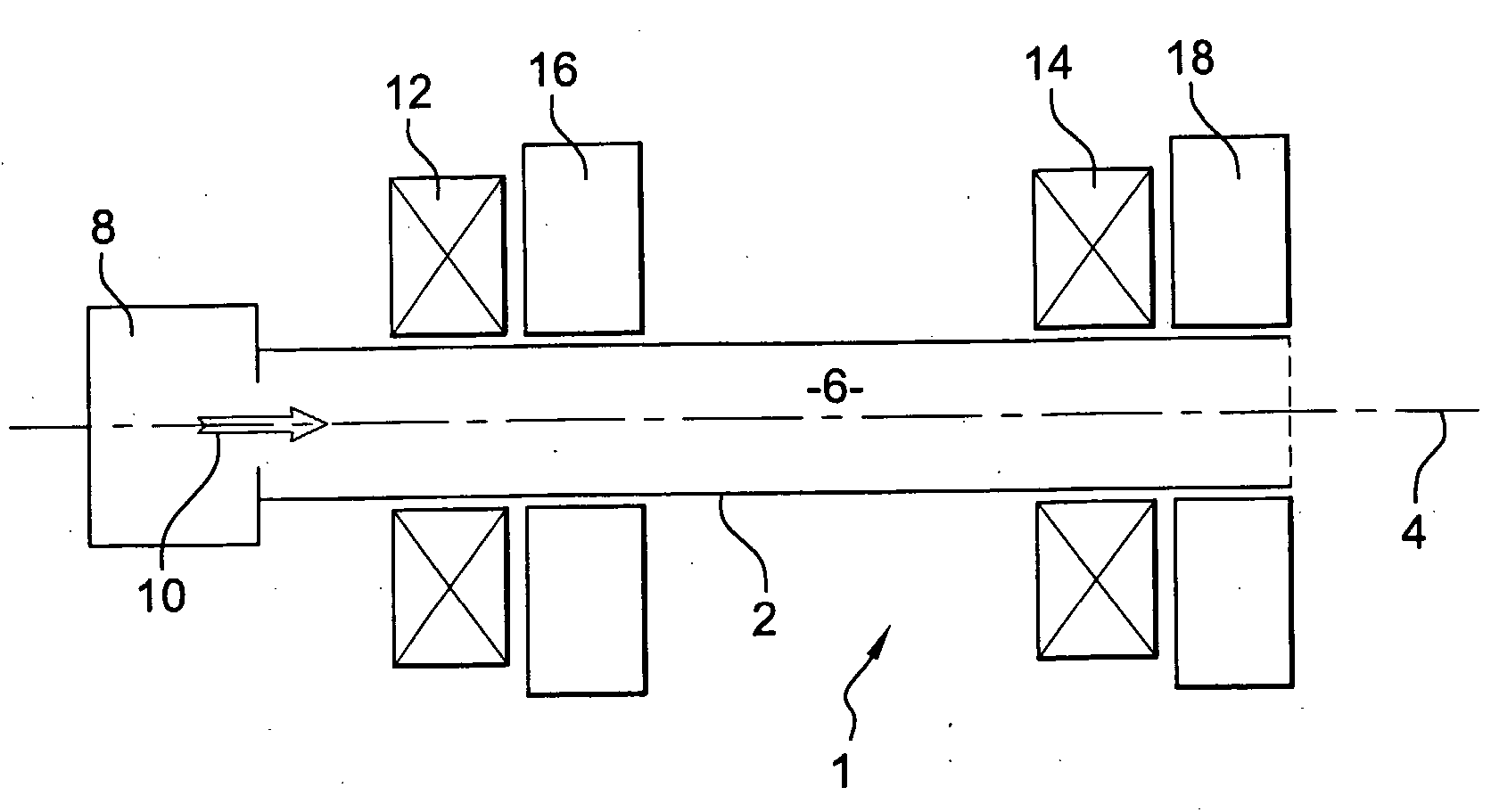
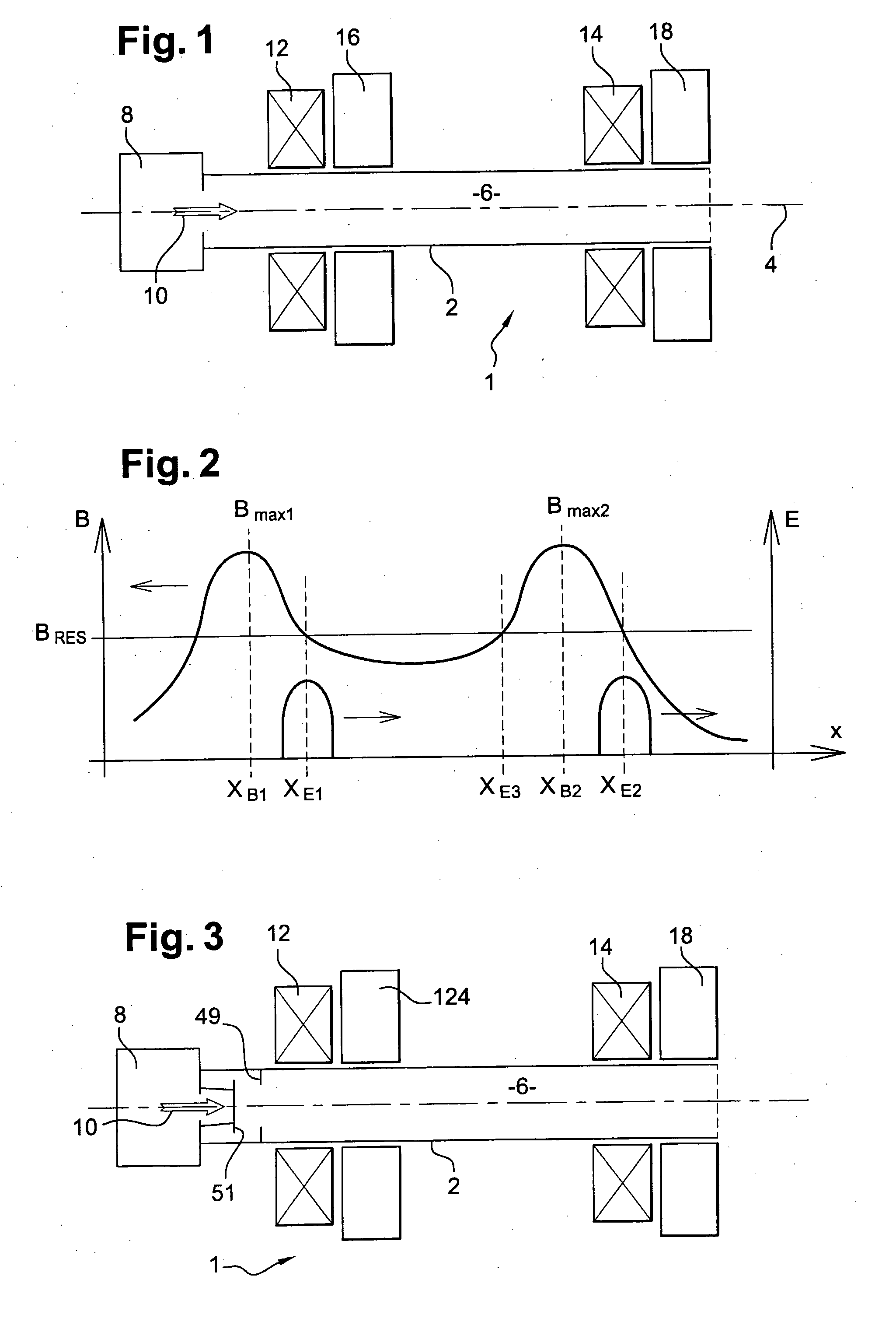
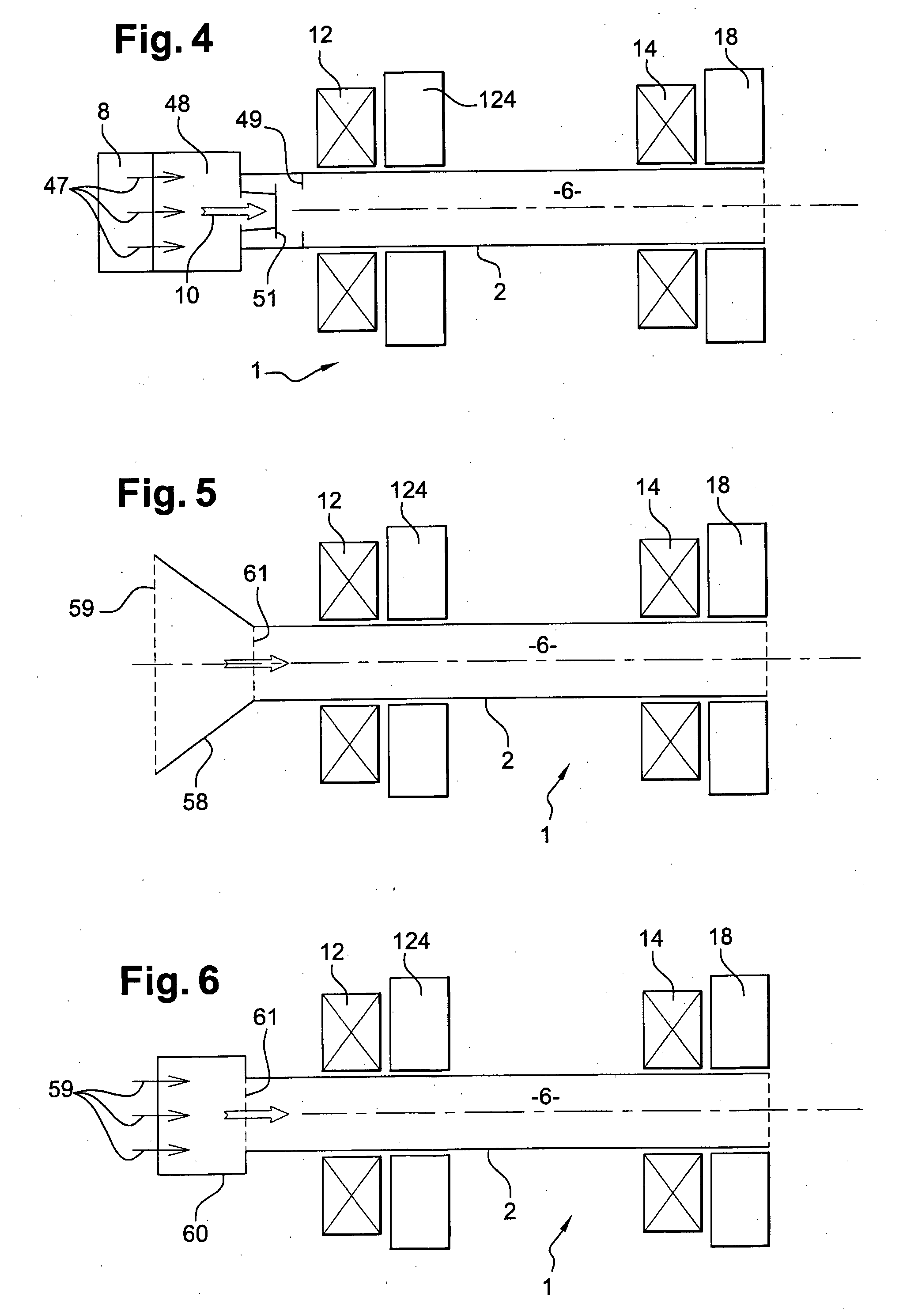
[0250]FIG. 3 is a schematic view in cross-section of a thruster 1 according to a first embodiment of the invention. The thruster 1 of FIG. 3 comprises obstruction means 50 between the injector 8 and the main chamber 6 adapted to obstruct partly the main chamber 6. In other words, FIG. 3 discloses a thruster 1, having first a main chamber 6 defining an axis 4 of thrust; second an injector 8 adapted to inject ionizable gas within the main chamber 6; third a ionizer 124 adapted to ionize the injected gas within the main chamber 6; fourth a first magnetic field generator 12, 14 and an electromagnetic field generator 18 adapted to generate a magnetized ponderomotive accelerating field downstream of said ionizer 124 along the direction of thrust on said axis 4; and fifth obstruction means 50, located downstream of the injector 8 and upstream of the ...


PUM


Abstract

A thruster (1) has a main chamber (6) defined within a tube (2). The tube has a longitudinal axis which defines an axis (4) of thrust; an injector (8) injects ionizable gas within the tube, at one end of the main chamber. An ionizer (124) is adapted to ionize the injected gas within the main chamber (6). A first magnetic field generator (12, 14) and an electromagnetic field generator (18) are adapted to generate a magnetized ponderomotive accelerating field downstream of said ionizer (124) along the direction of thrust on said axis (4),
The thruster (1) ionizes the gas, and subsequently accelerates both electrons and ions by the magnetized ponderomotive force.

Description

BACKGROUND AND SUMMARY OF THE INVENTION [0001] The invention relates to the field of thrusters. Thrusters are used for propelling spacecrafts, with a typical exhaust velocity ranging from 2 km / s to more than 50 km / s, and density of thrust below or around 1 N / m2. In the absence of any material on which the thruster could push or lean, thrusters rely on the ejection of part of the mass of the spacecraft. The ejection speed is a key factor for assessing the efficiency of a thruster, and should typically be maximized. [0002] Various solutions were proposed for spatial thrusters. U.S. Pat. No. 5,241,244 discloses a so-called ionic grid thruster. In this device, the propelling gas is first ionized, and the resulting ions are accelerated by a static electromagnetic field created between grids. The accelerated ions are neutralized with a flow of electrons. For ionizing the propelling gas, this document suggests using simultaneously a magnetic conditioning and confinement field and an electr...

Claims


Application Information

Patent Timeline
Patent Type & Authority Applications(United States)
IPC IPC(8): B64G1/26
CPCH05H1/54F03H1/0081
Inventor EMSELLEM, GREGORYLARIGALDIE, SERGE
Owner ELWING LLC
Why Eureka
Try Eureka