River and tidal power harvester

a technology of river and tidal power, applied in the field of energy, can solve the problems of severe liquid fuel shortages worldwide, increased absolute cost of carbon-based fuels, and incredibly small orbital changes that paced the ice age, and achieves low cost, low operational speed, and energy efficiency.

Inactive Publication Date: 2008-04-24
CATLIN CHRISTOPHER S
View PDF37 Cites 29 Cited by
  • Summary
  • Abstract
  • Description
  • Claims
  • Application Information

AI Technical Summary

Benefits of technology

[0093]The present invention relates to a river and tidal energy generation system. The invention is of a rugged and mobile design that is low cost and energy efficient. An array of interconnected energy devices designed for both river and tidal siting are arrayed across the path of the direction of the primary current so as to absorb and convert the largest spectrum of kinetic energy to pneumatic, mechanical or electric energy. The invention has a non-fouling, self-cleaning surface that repels both debris and marine growth. Its low operational speed, rounded surfaces and minimal mooring system provides the ultimate safety for wildlife. When loads approach the maximum the unit is designed to shed loads. It has a minimum number of parts to reduce costs and breakdowns as well as maximizing the use of available parts. It minimizes internal, inertial / mass, the number of energy conversion stages and surface friction to offer high overall energy conversion efficiency. It is easy to install and to remove and from its operational site. It is primarily made of recycled materials can be mass producible at low cost. No energy costs, fees, royalties, real estate tax are needed to be paid—river energy is both free and abundant. It produces no greenhouse gas (GHG) emissions, directly or indirectly.

Problems solved by technology

The search for new sources of energy has become the most important challenge for the new century.
The absolute cost of carbon-based fuels, particularly petroleum, has increased dramatically over the last decade along with the political and military consequences caused by the world's increasing reliance on it.
To lessen the impact, it concluded, we have to start a long time before the peak or we'll have severe liquid fuels shortages worldwide.
These orbital changes that paced the ice ages were incredibly small.
Nevertheless, these minute redistributions led to swings in temperature of about 5 degrees C. and variations in sea level of more than 100 meters.
Also we do not want an energy producing technology that fills up the countryside with machinery eyesores and noise.
Oil certainly does not meet these new requirements, nor does ethanol, biomass or even wind or conventional hydropower.
Many of the Third World countries suffer from polluted cities affecting their tourism, high petroleum import costs and growing power grid failures weakening their economies and their fragile currencies.
Besides the ecological consequences, the rise in oil prices represents a big redistribution of income from those who buy it to those who produce it.
The second most important challenge for the new century is clean water.
With water availability shrinking across the Middle East, Asia and sub-Saharan Africa, so the argument runs, violent conflict between states is increasingly likely.
By 2025, more than two billion people are expected to live in countries that find it difficult or impossible to mobilize the water resources needed to meet the needs of agriculture, industry and households.
In parts of India, groundwater levels are falling so rapidly that from 10 percent to 20 percent of agricultural production is under threat.
Although hydropower is a clean and unlimited source of energy, it often comes with a high price.
It is currently dominated by huge expensive dams which displace people, flood vast areas and wipe out fish populations that need open rivers to spawn.
Holding back further use of hydropower per has been the lack of an efficient, inexpensive and environmentally friendly device to extract energy from water.
Most dams also present insurmountable obstacles to the movement of aquatic species.
Possibly the major problem with dams is the long term threat to the viability of their reservoirs caused by excessive silting.
These high sediment loads also effect the operation of the plant by throttling the feeder tunnels, eroding guide vanes and runner blades.
As a result some coastlines are eroding at rapid rates.
Dams interrupt the ecology of the natural river system as well as degrade water quality.
Their turbines cause high fish mortality.
Tidal fences are not free of environmental and social concerns, as a caisson structure is still required, which can disrupt the movement of large marine animals.
Problems with river and tidal power.
(b) Some devices cannot be removable without damage to site;
(h) Due to their complexity most devices are limited to where they can be sited;
(i) Many devices are not swimmer and boat safe;
(j) Most devices are not safe for fish and river life;
(l) Many devices have high initial build costs;
(m) Many devices are limited to few river sites in terms of depth, width, speed of water, bottom shape;
(n) Some devices require costly high load capacity roads to be built to site;
(o) Many devices have complicated electrical systems requiring expensive and vulnerable seals;
(p) Most devices cannot be fabricated of recycled materials which decreases their total lifecycle energy costs;
(r) Most devices cannot meet the global strategy required to deal with the successful commercialization of a low-density global energy source.
(v) Some devices have high capital cost;
(y) Some devices are not safe for fish and tidal area life;
(z) Most devices have high initial build and operating costs;
(cc) Many devices are difficult to remove without damage to site;
(dd) Many devices do not produce enough energy returned to replace the total energy invested.
(ee) Some devices require extensive anchoring systems which are expensive, time consuming to install and affect marine life.

Method used


Image

  • River and tidal power harvester
  • River and tidal power harvester
  • River and tidal power harvester

Examples


Embodiment Construction

—FIGS. 1, 2, 3a, 3b, 3c, 3d, 4, 5, 6—PREFERRED EMBODIMENT

[0144]The following is a detailed description of illustrative embodiments of the present invention. As these embodiments of the present invention are described with reference to the aforementioned drawings, various modifications or adaptations of the methods or specific structures described may become apparent to those skilled in the art. All such modifications, adaptations, or variations that rely upon the teachings of the present invention and through these teachings have advanced the art, are considered to be within the spirit and scope of the present invention.

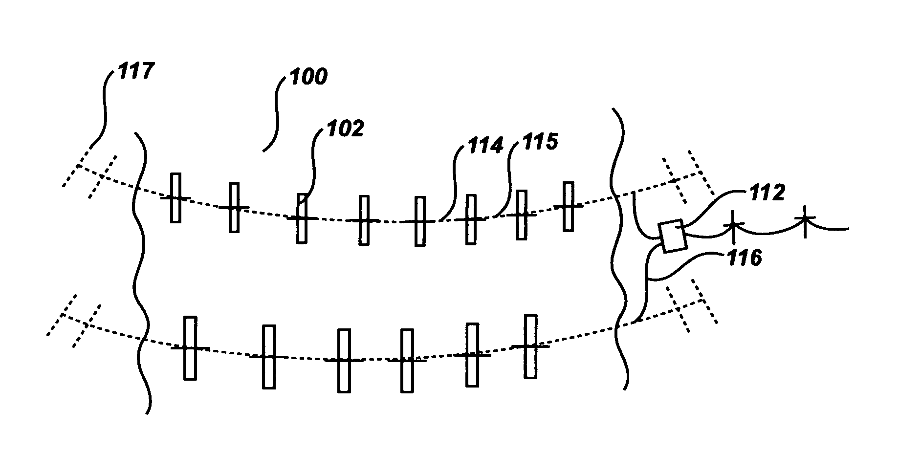
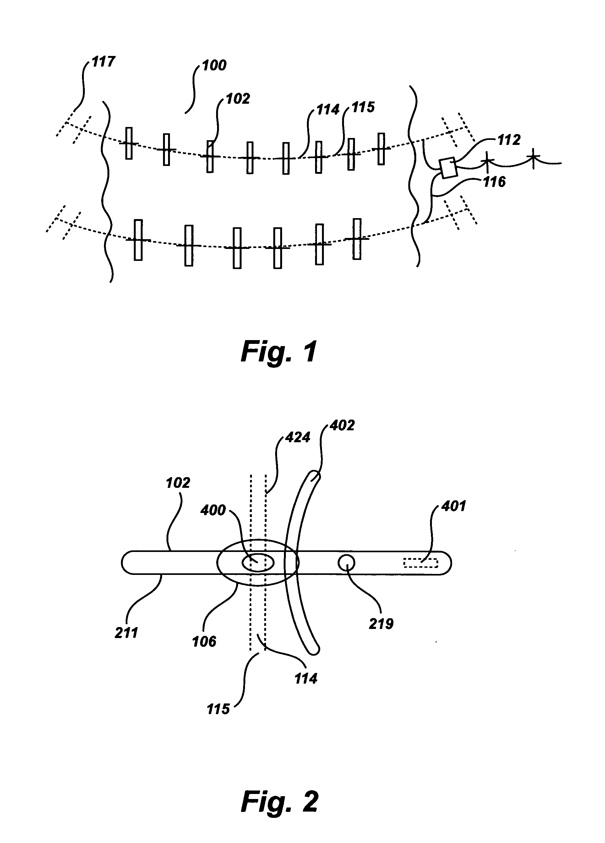
[0145]FIG. 1 is a top view of an Array of Devices 100 composed of a plurality of individual submerged and floating versions of the River and Tidal Energy Modules (the invention) 102 deployed across a river site. Each of the River and Tidal Energy Modules 102 is connected to another by a Mooring Cable 115 composed of an approximately three inch diameter high tensile s...


PUM


Abstract

An improved tidal and river energy converter having a semi-submerged device designed to harvest energy from the tidal and river sites. Each device is connected to other like devices to form an interconnected array of tidal and river energy devices that are anchored to the shore at right angles to the prevailing tidal and river current. Each device is composed of a supporting floatation hull attached to a submerged strut supporting an air compressor driven by a slow rotating propeller. The air compressor is connected through a streamlined mooring system to the other air compressors in the array and those in turn are connected to a high pressure line leading underwater to an onshore air turbine electric generator connected to the local power grid.

Description

CROSS-REFERENCE TO RELATED APPLICATIONS[0001]Not ApplicableFEDERALLY SPONSORED RESEARCH[0002]Not ApplicableSEQUENCE LISTING OR PROGRAM[0003]Not ApplicableBACKGROUND OF THE INVENTION[0004]1. Field of Invention[0005]This invention relates to the field of energy, specifically to a device that can produce mechanical, pneumatic and electrical energy from river and tidal hydropower sources with maximum efficiency, minimum cost and without producing any greenhouse gases (GHG) emissions.[0006]2. Prior Art[0007]Today, our energy economy seems to be humming along like a perpetual motion machine. Billions of people enjoy an unprecedented standard of living and nations are floating in rivers of wealth, in large part because, around the world, the energy industry has built an enormous network of oil wells, supertankers, pipelines, coal mines, power plants, transmission lines, cars, trucks, trains and ships—a gigantic, marvelously intricate system that almost magically converts oil and its hydroc...

Claims


Application Information

Patent Timeline
Patent Type & Authority Applications(United States)
IPC IPC(8): F03B13/00H02P9/04
CPCF03B13/264F03B15/00Y02E10/28F05B2240/93F05B2240/97F03B17/061Y02E10/30Y02E10/20
Inventor CATLIN, C.S.
Owner CATLIN CHRISTOPHER S
Why Eureka
Try Eureka