

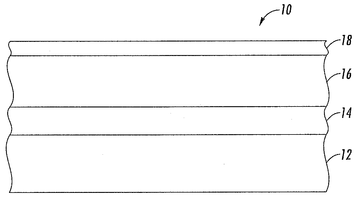
Imaging member
a technology of imaging members and members, applied in the field of imaging members, can solve the problems of repetitive cycling, adverse effects on the exposed portions of the imaging member, and deterioration in the mechanical and electrical characteristics of the exposed layers, and achieve the effects of satisfactory electrical properties, reducing lateral charge migration, and deleting and/or stress cracking
- Summary
- Abstract
- Description
- Claims
- Application Information
AI Technical Summary
Benefits of technology
Problems solved by technology
Method used
Image


Examples
example 1
[0062]An imaging member was prepared by providing a 0.02 micrometer thick titanium layer coated on a biaxially oriented polyethylene naphthalate substrate (KALEDEX™ 2000) having a thickness of 3.5 mils. A blocking layer was applied from a solution containing 50 grams 3-amino-propyltriethoxysilane, 41.2 grams water, 15 grams acetic acid, 684.8 grams of 200 proof denatured alcohol and 200 grams heptane. The blocking layer was then dried for about 2 minutes at 120° C. The resulting blocking layer had a dry thickness of 500 Angstroms.
[0063]An adhesive layer was applied from a solution containing 0.2 percent by weight based on the total weight of the solution of polyarylate adhesive (Ardel D100 available from Toyota Hsutsu Inc.) in a 60:30:10 volume ratio mixture of tetrahydrofuran / monochlorobenzene / methylene chloride. The adhesive layer was then dried for about 2 minutes at 120° C. The resulting adhesive layer had a dry thickness of 200 angstroms.
[0064]A charge generating layer dispersi...
example 2
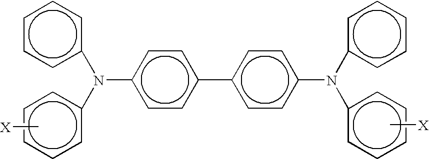
[0066]In a 250-ml brown bottle, 2.0 grams of the hole transport molecule N,N′-bis(4-methylphenyl)-N,N′-bis(4-ethylphenyl)-[1,1′-biphenyl]-4,4′-diamine, 2.25 grams of the polycarbonate PCZ-500, 0.45 grams of PTFE nanoparticles, 0.01 grams of the fluoro-surfactant GF-300, 0.4 grams of Bisphenol A glycerolate dimethacrylate, 0.1 grams of methacrylated silicone fluid, and 0.01 grams of free radical initiator AIBN were charged with 95 grams of tetrahydrofuran, then 50 grams of glass beads of 3 mm diameter were added. The bottle was set in a paint-shaker to mix the materials for 3 hours. Then, the solution was ready for coating.
example 3
[0067]In a 250-ml brown bottle, 2.0 grams of the hole transport molecule N,N′-diphenyl-N,N′-bis(3-methyl-phenyl)-(1,1′-biphenyl)-4,4′-diamine, 2.25 grams of the polycarbonate PCZ-500, 0.45 grams of PTFE nanoparticles, 0.01 grams of the fluoro-surfactant GF-300, 0.4 grams of Bisphenol A glycerolate dimethacrylate, 0.1 grams of methacrylated silicone fluid, and 0.01 grams of free radical initiator AIBN were charged with 95 grams of tetrahydrofuran, then 50 grams of glass beads of 3 mm diameter were added. The bottle was set in a paint-shaker to mix the materials for 3 hours. Then, the solution was ready for coating.
Fabrication of Photoreceptor Device with Overcoat
PUM
| Property | Measurement | Unit |
|---|---|---|
| Percent by mass | aaaaa | aaaaa |
| Percent by mass | aaaaa | aaaaa |
| Percent by mass | aaaaa | aaaaa |
Abstract
Description
Claims
Application Information