Polymer Composition, Plastic Optical Fiber, Plastic Optical Fiber Cable, and Method for Manufacturing Plastic Optical Fiber

Active Publication Date: 2008-07-10
MITSUBISHI CHEM CORP
View PDF2 Cites 8 Cited by
  • Summary
  • Abstract
  • Description
  • Claims
  • Application Information

AI Technical Summary

Benefits of technology

[0022]The polymer composition according to the present invention is excellent in heat resistance and transparency. The plastic optical fiber and the plastic optical fiber cable tha

Problems solved by technology

However, when POFs with polycarbonate resins (PC resins) as core material are to be produced, it is difficult to purify the core materials and remove foreign matters and the like.
These POFs further have large light scattering loss due to ununiformity of density of the polymers themselves.
Therefore, POFs with polycarbonate as core material tend to cause structural changes such as separation at the core-clad interfaces.
In addition, polymers having alicyclic groups in the main chains commercially available from several companies for core materials of POFs are difficult to purify.
POFs using the polymers as core material have suffered from problems such as inferior transmission characteristics, low adhesion between the core and the clad, or the like as well as the POFs with polycarbonate resins as core material.
Therefore, such POFs have a problem that the polymers cause heat deterioration when the polymers are melted and formed, thereby deteriorating transmission characteristics.
However, the homopolymers of α-methylene-γ-butyrolactone derivatives and the copolymers of the α-methylene-γ-bu

Method used


Image

  • Polymer Composition, Plastic Optical Fiber, Plastic Optical Fiber Cable, and Method for Manufacturing Plastic Optical Fiber
  • Polymer Composition, Plastic Optical Fiber, Plastic Optical Fiber Cable, and Method for Manufacturing Plastic Optical Fiber
  • Polymer Composition, Plastic Optical Fiber, Plastic Optical Fiber Cable, and Method for Manufacturing Plastic Optical Fiber

Examples


exemplary embodiment 1

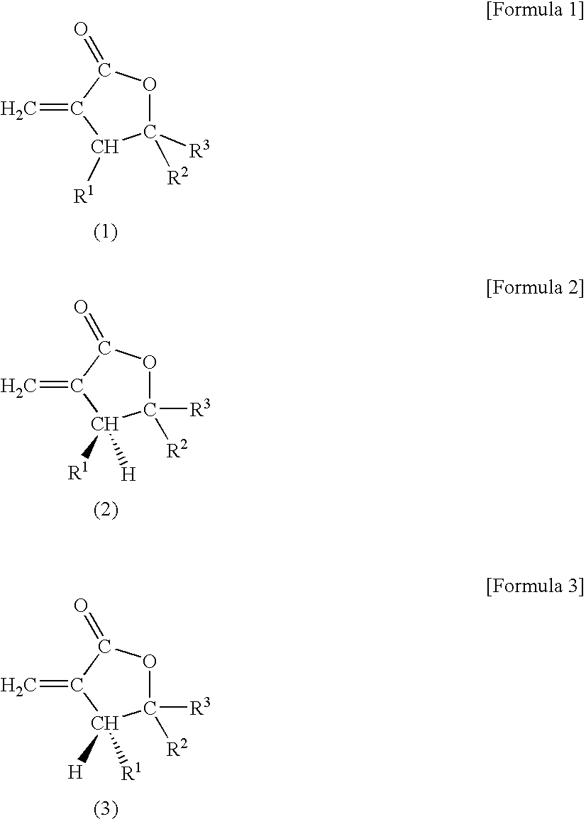
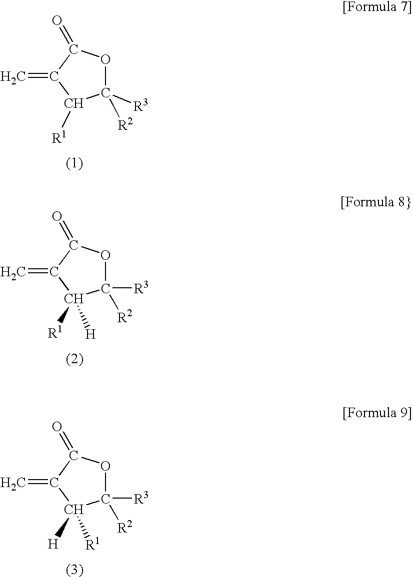
[0174]50 parts by mass of the (R)-βMMBL obtained in (Synthesis 7) and 50 parts by mass of the (S)-βMMBL obtained in (Synthesis 8) were combined to obtain a mixture of (R)-βMMBL and (S)-βMMBL ((R / S)-βMMBL) (h).

[0175]100 parts by mass of the (R / S)-βMMBL, 0.3 parts by mass of dimethyl 2,2′-azobis-isobutyrate (V-601) as a polymerization initiator, and 0.3 g parts by mass of n-butyl mercaptan as a chain transfer agent were placed in a beaker and stirred. This stirred and dissolved mixture was charged into a glass ampoule and dissolved oxygen was removed by repeating freezing and devolatilization five times. After that, the mixture was subjected to heat treatment at 65° C. for 12 hours in an oil bath and subsequently at 120° C. for 5 hours to complete polymerization.

[0176]The resulting bulk polymer was dissolved in methylene chloride, precipitated in methanol, filtered, washed with water and dried at 75° C. for 24 hours to obtain a polymer. After that, a twin-screw extruder (manufactured ...

exemplary embodiments 2 to 7

Comparative Examples 1 to 7

[0179]Polymerization, pelletization, preparation of test specimens, and evaluation of various items were conducted as with Exemplary Embodiment 1 except that composition of the mixture of (R)-βMMBL, (S)-βMMBL, and MMA were changed as shown in Table 1. Obtained evaluation results are summarized in Table 1.

exemplary embodiments 8 to 11

Comparative Examples 8 to 11

[0180]Polymerization, pelletization, preparation of test specimens, and evaluation of light transmittance were conducted as with Exemplary Embodiment 1 except that composition of the mixture of (R)-βMMBL, (S) -βMMBL, and MMA were changed as shown in Table 2. Obtained evaluation results are summarized in Table 2.


PUM

PropertyMeasurementUnit
Fractionaaaaaaaaaa
Percent by massaaaaaaaaaa

Abstract

There is provided a polymer composition comprising 5 to 100% by mass of a unit (A) of a lactone compound represented by a general formula (1) and 0 to 95% by mass of a unit (B) of (meth)acrylate as constitutional units, wherein the unit (A) of a lactone compound comprises a unit of an (S) isomer represented by a general formula (2) and a unit of an (R) isomer represented by a general formula (3) at a mass ratio of from 70/30 to 30/70; and wherein the polymer composition has a total light scattering loss of not more than 100 dB/km. The polymer composition is excellent in heat resistance and transparency.

Description

TECHNICAL FIELD[0001]The present invention relates to a polymer composition excellent in transparency and heat resistance, a plastic optical fiber, a plastic optical fiber cable, and a method for manufacturing plastic optical fiber.BACKGROUND ART[0002]Plastic optical fibers (POF) are in practical use in lighting applications, sensors for FA, or media for transmission of information in the communications industry by taking advantages of POFs such as low cost, lightweight, flexibility, and large diameter. As core material of POFs, a polymethyl methacrylate (PMMA) resin having sufficient mechanical strength and transmission characteristics is used as a main component.[0003]As for POF using PMMA as a core material, because PMMA has a glass transition temperature (Tg) of about 110° C., the POF can be used actually under temperatures of the upper limit of about 110° C. even when the outside of the POF is coated with a polymer having a higher heat resistance. Therefore, in applications tha...

Claims


Application Information

Patent Timeline
IPC IPC(8): G02B6/44C08F24/00
CPCG02B6/02033C08F224/00C08G63/08C08J3/00C08G63/91G02B6/00
Inventor AOYAGI, AMANETSUKAMOTO, YOSHIHIROIWASAKA, KEIJISAKASHITA, KEIICHI
Owner MITSUBISHI CHEM CORP
Why Eureka
Try Eureka