
Method of treating unburnt methane by oxidation by plasma

a plasma oxidation and unburnt technology, applied in gas treatment, chemical/physical/physicochemical processes, membrane technology, etc., can solve the problems of high cost, large volume of catalytic converters, and rapid deactivation of residual sulfur, so as to increase the conversion ratio of methane and plasma in combination with the catalyst.

Inactive Publication Date: 2008-07-24
GDF SUEZ SA +1
View PDF8 Cites 6 Cited by
  • Summary
  • Abstract
  • Description
  • Claims
  • Application Information

AI Technical Summary

Benefits of technology

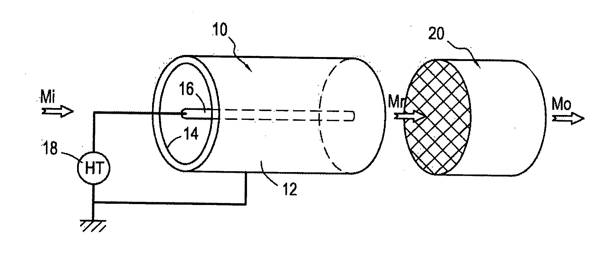
[0011]Secondly, the fact that one or the other of the electrodes of the plasma reactor is covered in a dielectric enables a dielectric barrier discharge to be created in the gas mixture within the plasma reactor. This has the advantage of limiting current through the plasma and of providing streamers that enable very high energy electrons to be obtained without significant transfer of heat.
[0014]This energy density range is advantageously selected to avoid parasitic reactions, such as the formation of NOx at high temperature. Thus, for a given temperature (e.g. 475° C.), a plasma energy density lying in the range 36 J / L to 58 J / L enables a better compromise to be obtained between unwanted formation of NOx and methane conversion.
[0017]Thus, by coupling a cold plasma with catalytic oxidation of residual methane, it is not necessary to heat the gas mixture for treatment above its natural temperature.
[0021]Unlike traditional methods where water has an inhibitor effect on the catalyst, the presence of water in accordance with the present invention has a promoter effect on the overall oxidation reaction. Thus, the conversion of methane with the plasma in combination with the catalyst is improved by the presence of water. In particular, water coming from the combustion of a fuel in the gaseous or liquid state lies behind the creation of highly reactive radicals such as OH• which have the effect of increasing the conversion ratio of the methane at the outlet from the catalytic device or at the outlet from the plasma reactor when it includes the catalyst.

Problems solved by technology

Nevertheless, the combustion of methane, which at 90% to 95% constitutes the major fraction of natural gas, can be incomplete.
Combustion with a lean mixture suffers mainly from low exhaust temperatures: the catalyst, based on palladium, needs to have a very large amount of precious metal and needs to be bulky in order to possess sufficient activity.
This leads to catalytic converters that are bulky, expensive, and rapidly deactivated by residual sulfur.
In contrast, the catalyst can be subjected to temperatures that are very high and can suffer strong thermal deactivation.

Method used


Image

  • Method of treating unburnt methane by oxidation by plasma
  • Method of treating unburnt methane by oxidation by plasma
  • Method of treating unburnt methane by oxidation by plasma

Examples


example 1

Effect of Energy Density on Methane Conversion

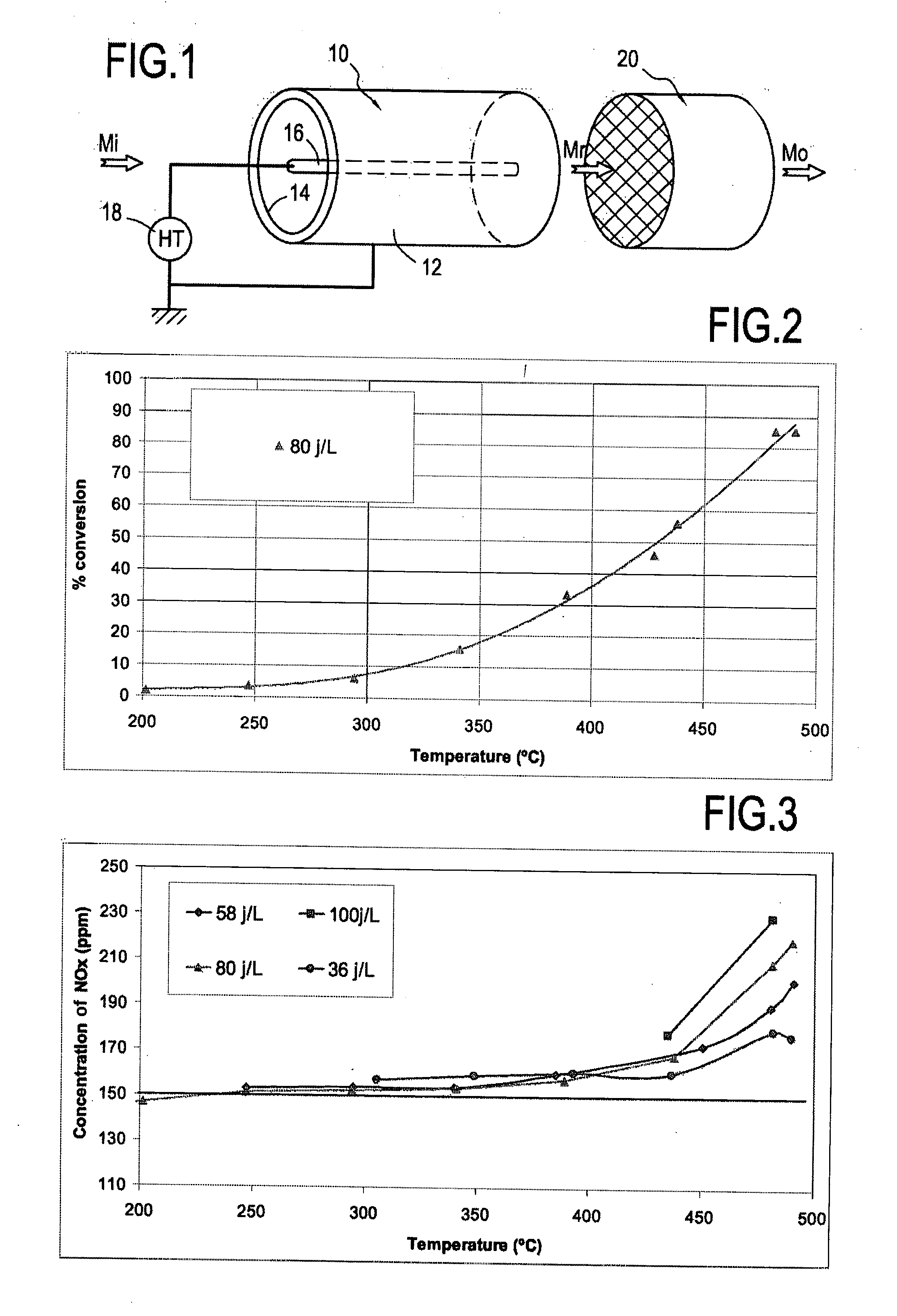
[0043]As shown in Table 1, the energy density of the plasma has an effect on methane conversion.

TABLE 1Methane conversion as a function of plasmaenergy density at 450° C.Energy density (J / L)15365880100Methane conversion (%)1839506375

[0044]In addition, the plasma creates NOx (FIG. 3) in the form of NO2 from 375° C., and the greater the energy density, the more NOx is formed. In the absence of CO2, the formation of NOx also begins at about 375° C. The best compromise between NOx formation and methane conversion is obtained for the densities 36 J / L and 58 J / L. It should be observed that the curves present an offset, that is merely the result of an initial presence of 150 ppm of NOx in the reaction mixture.

example 2

Effect of Water on Methane Conversion

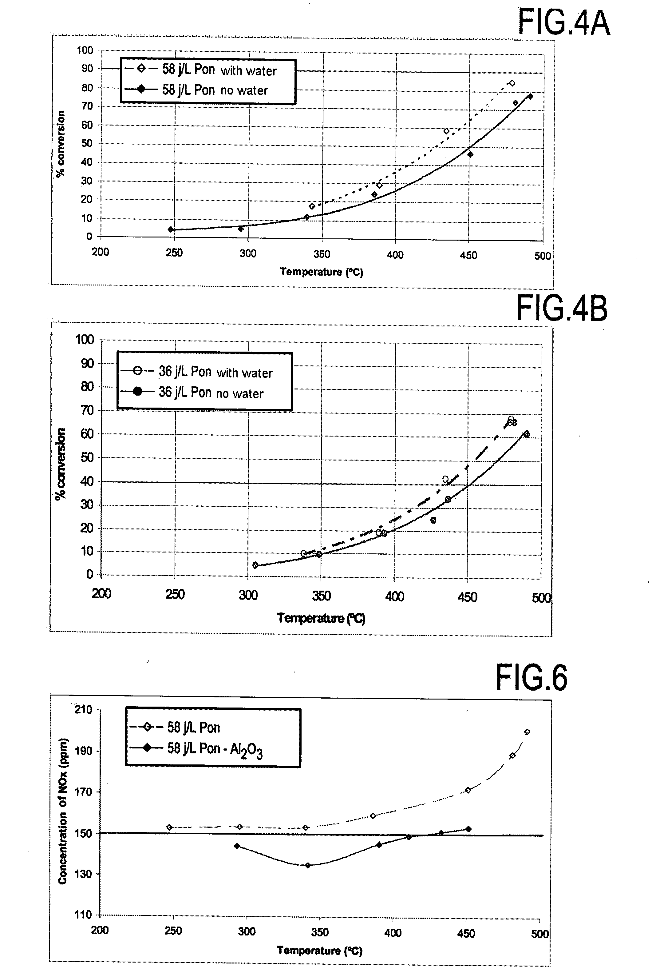
[0045]Water has a promoter effect on methane conversion by plasma in the presence of a catalyst, as shown in FIG. 2, unlike its well-known inhibitor effect on catalysts.

TABLE 2Effect of water on the activity of the plasma inoxidizing methane at 450° C.Energydensity (J / L)3658Methane conversion (%) without H2O3950Methane conversion (%) with H2O at 3% by volume4864

[0046]FIGS. 4A and 4B show the results obtained for temperatures lying in the range 250° C. to 500° C. with energy densities of 36 J / L and 58 J / L.

example 3

Catalytic Effect of Alumina (Al2O3)

[0047]The alumina studied was gamma alumina (reference catalyst support), having a specific surface area of 250 square meters per gram (m2 / g).

[0048]It is known that alumina on its own is weakly active in oxidizing methane from 425° C. At this temperature, alumina oxidizes CO into CO2.

[0049]With the invention, and as shown in Table 3, alumina presents a catalytic effect. Thus, at 450° C., more than 50% methane conversion was obtained with a plasma plus alumina system (D=36 J / L and VVH=20,000 h−1), whereas only 39% was obtained with the plasma on its own. Furthermore, conversion increased significantly with energy density (FIGS. 5A, 5B, and 5C). It should be observed that the formation of NOx was greatly reduced at high temperature when using plasma and alumina together, as compared with plasma on its own (FIG. 6).

TABLE 3Effect of plasma and Al2O3 (alumina) together onmethane conversion at 450° C.Energydensity (J / L)365880Methane conversion (%) plasma...


PUM


Abstract

A method of treating a methane residue in a gas mixture at a temperature lying in the range 200° C. to 500° C. and including at least methane at a concentration lying in the range 50 ppm to 2500 ppm and oxygen at a concentration lying in the range 0.5% to 12% by volume. According to the invention, the methane residue is treated by a plasma having energy density lying in the range 15 J / L to 100 J / L generated in a plasma reactor by applying a high voltage electrical signal between an internal electrode and an external electrode of the plasma reactor, the external electrode being cylindrical in shape and surrounding the internal electrode, and at least one of the electrodes being covered in a dielectric material to create a dielectric barrier discharge in the gas mixture and convert part of the methane residue into carbon monoxide.

Description

TECHNICAL FIELD[0001]The present invention relates to the field of treating gas effluents and more particularly it relates to treating methane residues coming from the combustion of natural gas or any type of liquid fuel (gasoline, diesel oil, heavy oil, etc.).STATE OF THE ART[0002]Six greenhouse-effect gases have been identified as having a significant impact on global warming: carbon dioxide CO2; methane CH4; nitrous oxide N2O; hydrofluorocarbons HFC; perfluorocarbons PFC; and sulfur hexafluoride SF6. Nevertheless, since methane has an impact on atmospheric warming that is 23 times greater than that of CO2 (for identical mass), it constitutes one of the greenhouse-effect gases that it is most advantageous to diminish.[0003]The combustion of natural gas by so-called fixed or stationary sources (gas turbines, boilers) is cleaner than the combustion of liquid fuels or coal. Nevertheless, the combustion of methane, which at 90% to 95% constitutes the major fraction of natural gas, can...

Claims


Application Information

Patent Timeline
Patent Type & Authority Applications(United States)
IPC IPC(8): B01J19/08
CPCB01D53/323B01D53/72B01D2259/818B01D2257/708B01D2257/702
Inventor DA COSTA, STEPHANIETENA, EMMANUELDA COSTA, PATRICKCHELHLO MARQUES, RUI MIGUEL JORGEDJAGA MARIEDASSOU, GERALD
Owner GDF SUEZ SA
Learn More