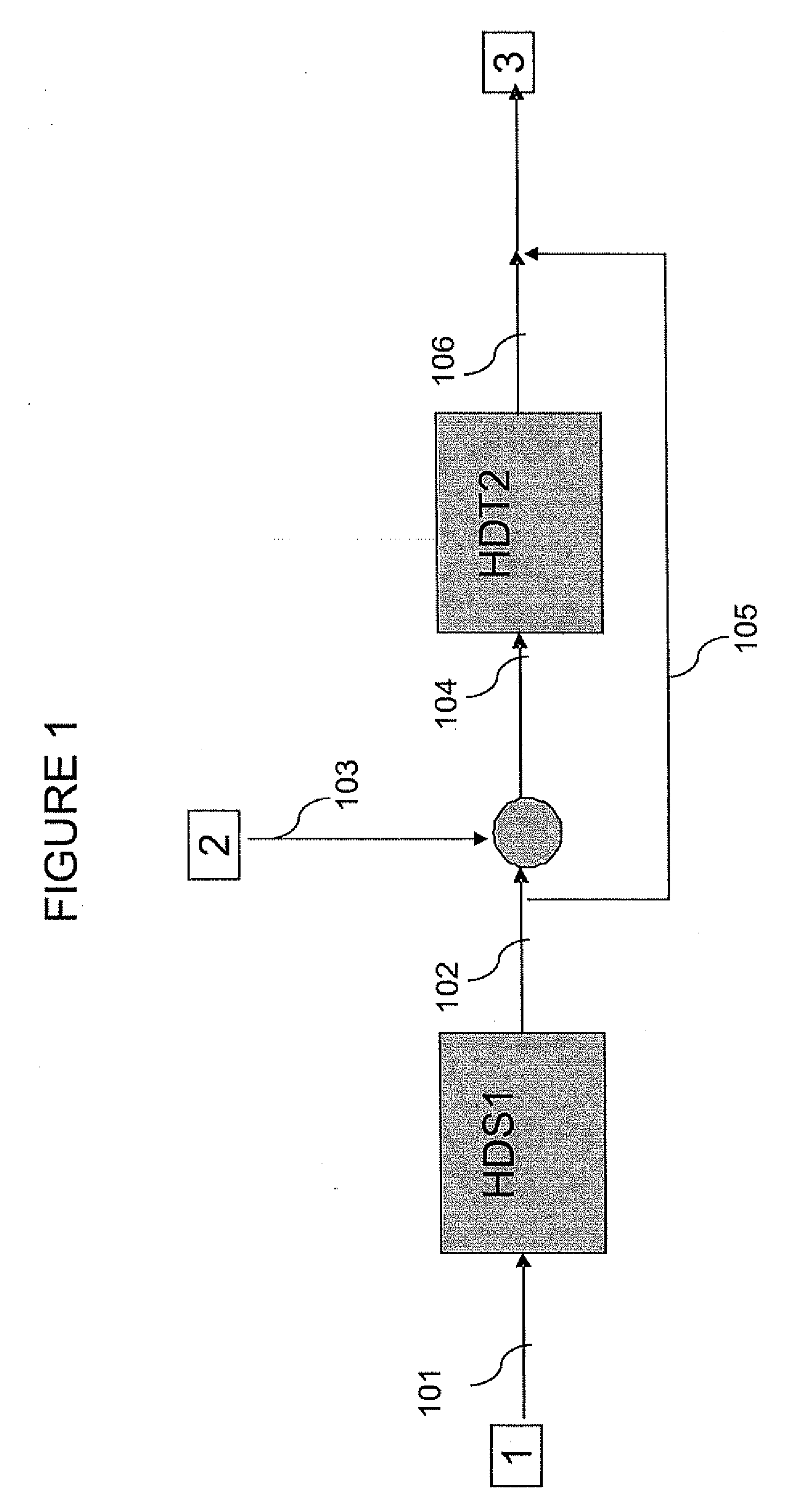
Methods of hydrotreating a mixture made up of oils of animal or vegetable origin and of petroleum cuts with quench injection of the oils on the last catalyst bed

a technology of oil cut and mixture, which is applied in the direction of hydrocarbon oil cracking, hydrocarbon oil cracking, organic chemistry, etc., can solve the problems of significant cosub>2 /sub>emission, negative environmental effects, and the search for new renewable energy sources that can be integrated into the conventional refining and fuel production scheme, so as to reduce the cost of treatment and reduce the cost of the treatment. , the cost of vegetable oil treatment in order to obtain gas oils meeting specifications

Active Publication Date: 2008-07-24
INST FR DU PETROLE
View PDF4 Cites 112 Cited by
  • Summary
  • Abstract
  • Description
  • Claims
  • Application Information

AI Technical Summary

Benefits of technology

[0027]Implementation of the method according to the invention allows to reduce the cost of the treatment of oils of vegetable or animal origin to obtain gas oils meeting the specifications in comparison with a specifically dedicated transesterification type plant, by integrating their treatment in an existing refining scheme with an existing hydrodesulfurization plant (HDS1).
[0028]The cost of the treatment of vegetable oils in order to obtain gas oils meeting specifications can also be reduced in relation to a co-treatment scheme in one or two stages because the streams of oil of vegetable or animal origin are small in relation to the streams of middle distillates that can be treated in a standard refinery. The costs of the utilities of the second plant of smaller size than the first are reduced since the oils are only in comixture with a small part of the hydrotreated hydrocarbon stream from the first stage.
[0029]The method according to the invention also allows to reduce the cost of the treatment of oils of vegetable or animal origin by incorporating their treatment on the one hand in an existing refining scheme comprising a hydrodesulfurization plant (HDS1), and on the other hand after the prior deep hydrodesulfurization stage, thus avoiding the inhibiting effects generated by the by-products resulting from the conversion of the oils (CO, CO2, etc.) in this first plant in relation to a single-stage co-tr

Problems solved by technology

In an international context characterized by a fast growth in fuel requirements, in particular gas oil bases in the European community, the search for new renewable energy sources that can be integrated in the conventional refining and fuel production scheme is a major challenge.
Furthermore, the processes known to date that use vegetable oils or animal fat are the cause of significant CO2 emissions, known for their negative effects on the environment.
Unsuitable for directly feeding modern diesel engines, these vegetable oils first have to be converted.
However, this type of process is relatively expensive and it requires vegetable oil type limitations in order to meet the biodiesel specifications.
Besides, the feeds for this type of process must be carefully selected, so that a certain number of vegetable oils cannot be treated in this manner.
Finally, the cold properties of these products also represent a limiting factor.
Furthermore, these two patents have the major drawback of a high hydrogen consumption essentially due to the unsaturations present in the feeds consisting of vegetable oils and to the fact that the oxygen contained in the triglycerides is generally decomposed by hydrodeoxygenation in the presence of a hydrotreating catalyst.
Besides, operating at such temperatures increases the risks of polymerization of the vegetable or animal feeds containing many unsaturations, which leads to the formation of solid particles causing operability problems for fixed-bed plants.
The products formed by means of this method are not directly used as fuel bases because of very poor cold properti

Method used


Image

  • Methods of hydrotreating a mixture made up of oils of animal or vegetable origin and of petroleum cuts with quench injection of the oils on the last catalyst bed

Examples


example 1

[0078]Single-Stage Method of Hydrotreating a Mixture Made Up of Vegetable Oils and of a Petroleum Cut

[0079]Co-treatment of a mixture made up of a straight-run gas oil and of a rape oil was carried out in a fixed-bed isothermal plant of descending flow type containing 50 cc catalyst of CoMo / Al2O3 type in dense loading.

[0080]The petroleum feed used is a straight-run gas oil from a Middle East crude whose characteristics are as follows:

Density at 15° C.:0.8522Sulfur:1.35% by weightNitrogen:126 mg / kgSimulated distillation:PI:155° C.10% by weight:247° C.50% by weight:315° C.90% by weight:392° C.PF:444° C.

[0081]After in-situ sulfurization at 350° C. in the plant under pressure, carried out by adding 2% by weight of dimethylsulfide to the gas oil feed used, hydrotreatment was then performed for 140 h under the following operating conditions:

Total pressure (MPa rel):4 MPaTemperature (° C.):350H2 / HC (Nl / l):320HSV (h−1):1.6

[0082]The properties of the effluents obtained are given in Table 1.

[0...

example 2

[0091]Treatment of the Vegetable Oil Alone

[0092]Hydrotreatment of a DNS grade quality rape oil was carried out in an isothermal plant consisting of a fixed bed of descending flow type containing 50 cc catalyst of NiMo / Al2O3 in dense loading.

[0093]The characteristics of the straight-run gas oil are identical to those of the gas oil of Example 1. After in-situ sulfurization carried out at 350° C. in the plant under pressure by addition of 2% by weight of dimethyldisulfide to the straight-run gas oil, the feed was modified for a feed consisting of 100% rape oil. The hydrotreatment test was then conducted under the following operating conditions for 150 h:

Total pressure (MPa rel):4 and 2.5 MPaTemperature (° C.):320, 300, 280H2 / HC (Nl / l):320HSV (h−1):1.6

[0094]The hydrogen consumption and the amount of CO and CO2 formed are shown in Table 2.

TABLE 2Two-stage hydrotreatment with inter-stage separation of a DNS grade qualityrape oilT = 320° C.T = 300° C.T = 300° C.T = 280° C.FeedP = 4 MPaP =...

example 3

[0098]Analysis of the Used Catalysts Used in Examples 1 and 2

[0099]The used catalysts described in Example 1 for a feed consisting of a hydrocarbon cut that contains no vegetable oil and for a feed comprising 15% vegetable oil were analyzed.

[0100]The results of the elementary analyses of these catalysts after toluene reflux washing and 1-hour drying in a vacuum drier are given in Table 3. It can be observed that the introduction of rape oil in the feed accelerates coking of the catalyst used and that the S / Mo ratio that characterizes the stability of the sulfide phase decreases. Aging of the catalyst is thus accelerated by the presence of vegetable oil in comixture.

[0101]The specific surface area of these used catalysts was also measured by means of the BET method. It was observed that the introduction of rape oil in the feed leads to a decrease in the specific surface area of the used catalysts.

[0102]The characteristics of the used catalyst described in Example 2 are also given in ...


PUM


Abstract

A hydrotreating method uses two catalyst beds with the introduction, on the last catalyst bed, of oils of animal or vegetable origin for co-treating a mixture made up of oils of vegetable or animal origin and of petroleum cuts (gas oil cuts (GO) and middle distillates) in order to produce gas oil effluents meeting specifications with an improved cetane number. The first catalyst bed is dedicated to only the deep desulfurization reactions (HDS1) of a petroleum type feed. The effluents of the first catalyst bed having an effluent sulfur content below or equal to 50 mg/kg are separated into two streams. The first stream, which is predominant, is sent to the gas oil pool. The second stream is mixed with oils of vegetable or animal origin. The resultant oil-petroleum cut mixture is then subjected to a milder hydrotreatment (HDT2). The effluents obtained at the outlet of the second catalyst bed can optionally be mixed with the predominant stream from the first bed. The process economy, the tolerance to the specifications relative to oils of animal or vegetable origin and the quality of the products obtained are thus greatly improved.

Description

FIELD OF THE INVENTIONCross Reference to Related Application [0001]This application is related to our concurrently filed application entitled “Methods Of Hydrotreating A Mixture Made Up Of Oils Of Animal Or Vegetable Origin And Of Petroleum Cuts With Intermediate Stripping”, attorney Docket No. PET-2449 claiming priority of French application FR 06 / 11409 filed Dec. 12, 2006.[0002]The present invention relates to methods of hydrotreating a feed made up of a mixture of oils of vegetable or animal origin and of petroleum feeds intended to produce gas oil fuel bases.BACKGROUND OF THE INVENTION[0003]In an international context characterized by a fast growth in fuel requirements, in particular gas oil bases in the European community, the search for new renewable energy sources that can be integrated in the conventional refining and fuel production scheme is a major challenge.[0004]In this respect, integration in the refining process of new products of vegetable or animal origin, resultin...

Claims


Application Information

Patent Timeline
IPC IPC(8): C10G47/00
CPCC10G45/02C10G3/54C10G2300/1011C10G2300/4018C10G3/46C10G3/50C10G2300/1014C10G2300/1018C10G2300/202C10G2300/1044C10G2300/1055C10G2300/301C10G2300/4006C10G2300/4012C10G2300/42C10G45/08C10G49/002C10G65/04Y02P30/20
Inventor MARCHAND, KARINBERTONCINI, FABRICE
Owner INST FR DU PETROLE
Why Eureka
Try Eureka