Apparatus and method for monitoring and measurement of droplets

a technology of droplet monitoring and measuring apparatus, which is applied in the direction of analytical using chemical indicators, laboratory glassware, instruments, etc., can solve the problems of inability to monitor the visual arrival of a tiny drop on a destination substrate, difficulty in consistent dispensing, and incorrect diagnosis

Active Publication Date: 2008-08-07
LABCYTE
View PDF17 Cites 24 Cited by
  • Summary
  • Abstract
  • Description
  • Claims
  • Application Information

AI Technical Summary

Benefits of technology

[0033]Furthermore, the present invention has advantageously recognized that droplets dispensed in this size range have different characteristics to droplets outside this general size range. For example, ink used in ink jet printing when dispensed will form a sphere-like shape and its volume can be calculated by the simple relationship between the volume and size. This is expanded on above. However, this simple relationship is not true of liquid droplets dispensed according to the present invention and this is expanded on in detail in the Detailed Description below. The present invention advantageously addresses this aspect.
[0034]It will be understood that the present invention is concerned with monitoring and measuring a liquid jet as it is dispensed when the jet is in the form of a cylindrical jet or quasi-cylindrical jet, or anywhere in between these two forms. Furthermore, for the purposes of this invention, the term “quasi-cylindrical” will be understood to also encompass the liquid jet when it is in the form of a series of sub-droplets which are of the same size with equal separation between the droplets, immediately prior to the formation of distinct spherical droplets or sub-droplets from the dispensed jet. Thus, the “quasi-cylindrical jet” according to the present invention, encompasses the liquid jet before it becomes one or more droplets (FIG. 2c).
[0035]It is also important to note that the term “quasi-cylindrical” covers both liquids dispensed from circular and / or non-circular nozzles. For example, a nozzle may have opening of any cross-section, including circular, square, rectangular or oval cross-sections. As capillaries of circular cross-section are readily available from numerous manufacturers of capillaries, these are generally used in practice. It will be understood that even if a jet is ejected from a non-circular nozzle, it will evolve to the circular cross-section due to the action of surface tension as it travels away from the nozzle. This will normally happen after several oscillations of the cross-sectional shape taking place as the jet travels away from the nozzle.
[0036]According to one embodiment of the invention, the method is carried out as the liquid jet is discharged from the liquid dispensing system.
[0037]Ideally, the cylindrical or quasi-cylindrical volume of a dispensed liquid jet is monitored and / or measured before the dispensed liquid jet becomes one or more distinct droplets, such as distinct spherical droplets. Thus, the liquid jet may be monitored as a series of sub-droplets.
[0038]Ideally, the method comprises providing an optical sensing unit at a distance from the liquid dispensing tip such that the liquid jet is sensed substantially as a cylindrical or quasi-cylindrical jet segment dispensed from the tip, and measuring the change in optical signal output from the optical sensing unit to determine the volume of the liquid jet.

Problems solved by technology

The wide variety of the mechanical properties of liquids and the very nature of many biological liquids often make consistent dispensing difficult.
For example, failure to dispense a drop may lead to an incorrect result of a medical test and consequently to incorrect diagnosis.
The reason is that in many cases the operator cannot readily monitor visually arrival of a tiny drop to a destination substrate, in particular, if the destination substrate is not flat.
This adds to the user discomfort even if the dispenser functions properly as the user cannot readily satisfy this by simple visual monitoring.
It is difficult to fulfil challenging requirements for a successful system for measurement of droplet volume during dispensing.
For many applications the ideal system must measure the volume in non-contact mode meaning that direct transfer of the drop to a measurement device, such as microbalance, is not an option.
The disadvantage of this method is that it is based on the absorption of electromagnetic radiation (in practice light) by the droplet.
For a range of applications where minute droplets of liquids with a broad range of optical properties need to be dispensed may present a challenge.
Another limitation of U.S. Pat. No. 5,559,339 (Domanik) is that for many applications it is desirable not only to confirm that a droplet has been dispensed but also extract information on the size of the droplet, and its velocity and shape.
Therefore many approaches developed for the applications in ink jet printing are not suitable for the field of dispensing for life science and drug discovery.
These inventions usually do not teach how more complex analysis of the droplet could be obtained from the measurements.
One of the disadvantages is that it is sensitive to external electromagnetic noise, e.g. noise at 50 or 60 Hz frequency.
This increases the chances of missing the exit hole and thus leaving the drop attached to the wall of the inner chamber.
Another disadvantage is that in order to increase the charge carried by the droplet and thus improve the sensitivity of the instrument, it is often necessary to apply as high a voltage to the dispenser as possible.
This may create further complications; e.g. the risk of destroying a charge sensitive amplifier connected to the pail, the risk of the malfunctioning of high voltage equipment with consequent danger for the operator, etc.
The key problem with the many of the droplet volume measurement inventions for the field of low volume liquid handling in life science is the low conductivity of many relevant liquids.
Unlike in the case of the ink jet printing where the formulation of the ink could be modified to suit the requirements of the printer, in the area of life sciences it is often not possible to change the formulation of the liquid.
Therefore, there is no simple way to increase its conductivity.
Unfortunately, this method can only be used with a specific type of the dispensing apparatus.
To summarise, at present the issue of reliable detection and measurement of the volume of droplets dispensed for applications in life science, medical diagnostics, drug discovery and pharmaceutical areas is still not fully resolved.
It is suggested that the lack of a commonly acceptable measurement technology impedes wider use of low-volume liquid handling equipment.

Method used


Image

  • Apparatus and method for monitoring and measurement of droplets
  • Apparatus and method for monitoring and measurement of droplets
  • Apparatus and method for monitoring and measurement of droplets

Examples


first embodiment

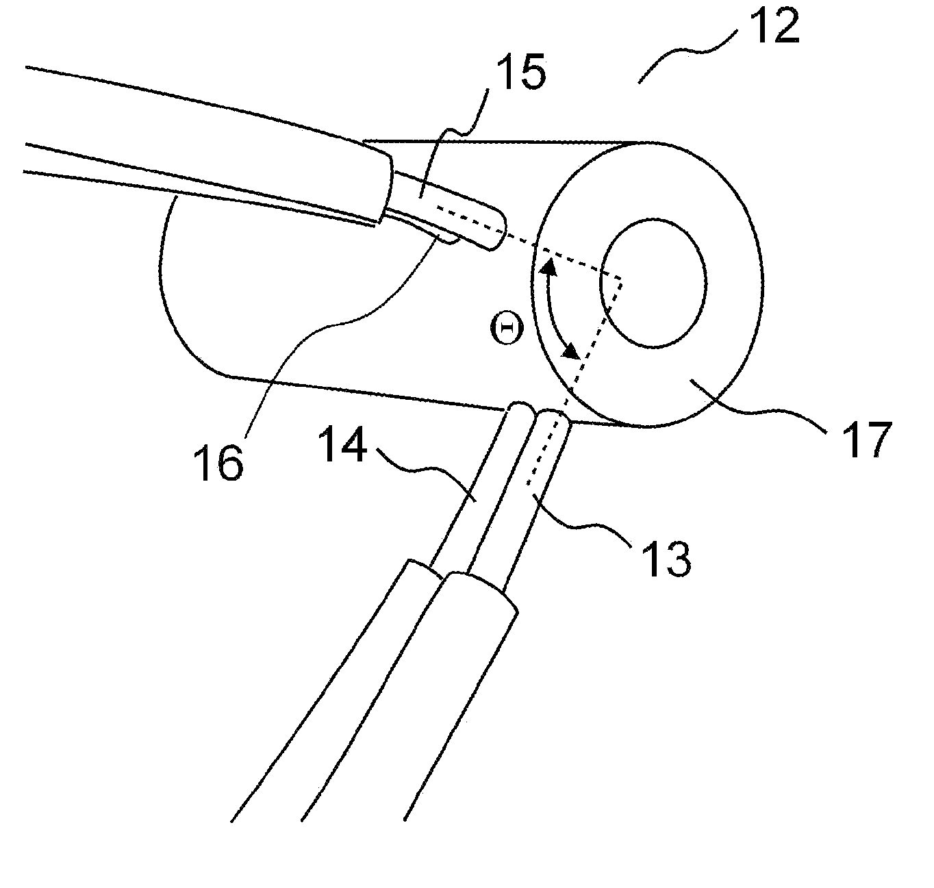
[0143]the method is based on measurement of the jet length lj. It is explained with reference to FIG. 25. At a relatively short distance away from the nozzle the jet in the typical volume range of interest to the field of the invention can be represented as a cylindrical segment. The diameter of the jet 2R0 (twice the radius) is typically essentially equivalent to the inner diameter (2r) (twice the radius) of the nozzle and it is uniform throughout the length of the jet segment. We shall explain later what defines the difference between the diameter of the jet 2R0 and the inner diameter of the nozzle 2r. Then the cross-sectional area of the jet is πR02. Therefore the volume of the jet is substantially equal to Vj=ljπR02. The length of the jet segment lj can be measured from the signal at the output of the phase sensitive detectors 25 and 26: lj=vjtj. Here tj is the time required for the jet segment to pass in front of the optical fiber, e.g. fiber 14 or fiber 13 and vj is the veloci...

second embodiment

[0144]the method is explained with reference to FIG. 26. The measurement is based on the signal from the output of a single phase sensitive detector 26. The signal from the second phase sensitive detector 25 is not required for this embodiment. Therefore this embodiment is based on just one set of fibers, e.g. 15 and 13 (or equally, fibers 14 and 16), one light source and one light detector. The jet velocity is measured using a signal slope. For example if the sensing area of the fiber 15 ls is 1 mm and the time of the signal rise tr is 30×10−5 sec, then the jet velocity is vj=ls / tr=3.3 m / sec. The jet length lj is determined as above using the value of the time tj. The values of tr and tj are schematically indicated in FIG. 26. Again we do not discuss the methods for the extraction of the values of tr and tj from the signal profile. The extraction could be achieved by means of analogue circuits, e.g. integrating and differentiating circuits or by means of conversion of the signal in...


PUM


Abstract

The present invention is directed to a liquid droplet monitoring and measuring apparatus for use with a liquid dispensing system of the type comprising a nozzle having a liquid dispensing tip and means for delivering the dispensed liquid through the nozzle onto a receiving substrate. Further, the invention provides a method of monitoring and measuring the volume of a liquid droplet as it is being dispensed from a liquid dispensing system comprising a nozzle having a dispensing tip. The main use for the invention is in the fields of drug discovery, genomics, medical diagnostics and other life science-related applications. The invention could also be used in other areas for example in the food industry, cosmetic industry or the chemical industry.

Description

CROSS-REFERENCE TO RELATED APPLICATION[0001]This application claims right of priority to Irish Application No. 2006 / 0943, filed Dec. 21, 2006, which is hereby incorporated herein by reference.FIELD[0002]The present invention relates to a liquid droplet monitoring and measuring apparatus for use with a liquid dispensing system of the type comprising a nozzle having a liquid dispensing tip for delivering the liquid through the nozzle onto a receiving substrate. Further, the invention provides a method of monitoring and measuring the volume of a liquid droplet as it is being dispensed from such a liquid dispensing system.[0003]The prime field of use of the invention is in drug discovery, genomics, medical diagnostics and other life science-related applications. However, it is also contemplated that the invention may also be used in many other fields where dispensing of small droplets in the volume range of, for example, approximately 1 nanoliter to approximately 1000 microliters or eve...

Claims


Application Information

Patent Timeline
Patent Type & Authority Applications(United States)
IPC IPC(8): G01F1/00G01F1/7086
CPCB01L3/0241B01L2200/061B01L2200/0615B01L2200/143B01L2200/148G01N35/1016G01F1/7086G01F13/008G01F15/075G01F15/0755B01L2300/0654
Inventor SHVETS, IGOR V.FRANKEN, CECILIAZAWADA, TOMASZ P.
Owner LABCYTE
Why Eureka
Try Eureka