Naphthalene compound and organic light-emitting device using the compound
a technology compound, which is applied in the direction of discharge tube luminescnet screens, other domestic articles, organic chemistry, etc., can solve the problems of insufficient resolution, large number of problems in the durability of organic light-emitting devices, and it is difficult to say that a compound capable of satisfying emission luminance and durability has been obtained, etc., to achieve good durability, high efficiency, and high luminance
- Summary
- Abstract
- Description
- Claims
- Application Information
AI Technical Summary
Benefits of technology
Problems solved by technology
Method used
Image
Examples
example 1
[0093](Synthesis of Exemplified Compound A-G-1)
[0094]The below-mentioned reagents and solvents were placed in a 100 mL reaction vessel, and the solution was heated to 90° C. and was stirred at the temperature for 10 hours.[0095]XX-2: 1 g (4.06 mmol)[0096]XX-1: 780 mg (1.84 mmol)[0097]Toluene: 20 mL[0098]2N aqueous solution of cesium carbonate: 20 mL[0099]Ethanol: 10 mL[0100]Tetrakistriphenylphosphinepalladium[0]: 234 mg (0.203 mmol)
[0101]The solution was cooled to room temperature, and the precipitated crystal was filtrated, whereby a coarse crystal was obtained. The coarse crystal was recrystallized from o-dichlorobenzene, whereby 650 mg of Exemplified Compound A-G-1 was obtained (67% yield).
[0102]With electron ionization mass spectrometry (EI-MS), it was confirmed that the compound had an M+ of 528.
[0103]1H-NMR(CDCl3, 500 MHz)σ(ppm): 8.17(m, 2H), 8.10(d, 2H), 8.04(d, 2H), 8.03(d, 2H), 7.99(d, 2H), 7.95(m, 4H), 7.83(dd, 2H), 7.76(d, 2H), 7.65(dd, 2H), 7.41(m, 4H)
[0104]In addition, ...
example 2
[0105](Synthesis of Exemplified Compound B-F-1)
[0106]The below-mentioned reagents and solvents were placed in a 100 mL reaction vessel. The solution was heated to 90° C., and was stirred at the temperature for 10 hours.[0107]XX-1: 2 g (4.72 mmol)[0108]XX-3: 4 g (10.4 mmol)[0109]Toluene: 30 mL[0110]2N aqueous solution of cesium carbonate: 30 mL[0111]Ethanol: 15 mL[0112]Tetrakistriphenylphosphinepalladium[0]: 620 mg (0.54 mmol)
[0113]The solution was cooled to room temperature. After that, 50 ml of saturated brine were added to the solution, and the mixture was extracted with toluene (50 mL×3 times). The organic layer was washed with saturated brine, and was then dried with sodium sulfate. After the desiccant had been removed by filtration, the filtrate was concentrated. After that, the concentrate was separated and purified by silica gel column chromatography (mobile phase: toluene), whereby a colorless coarse crystal was obtained. The coarse crystal was recrystallized from a mixture ...
example 3
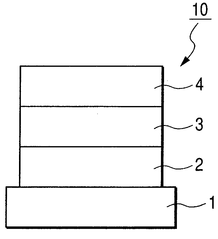
[0130]An organic light-emitting device having three organic layers shown in FIG. 3 was produced.
[0131]On a glass substrate (substrate 1), a film of indium tin oxide (ITO) was formed in a thickness of 100 nm and patterned as the anode 2, whereby a transparent substrate having an ITO electrode was produced. On the transparent substrate with the ITO electrode, layers each including an organic compound and a cathode were continuously formed by vacuum evaporation using resistive heating. To be specific, first, as the hole-transporting layer 5, a film of α-NPD shown below was formed in a thickness of 40 nm by evaporation. Next, as the light-emitting layer 3, a film was formed by coevaporation of HOST-1 as a host and Exemplified Compound A-G-1 as a guest in such a manner that the content of Exemplified Compound A-G-1 was 10 wt % of the entirety of the light-emitting layer. At this time, the light-emitting layer had a thickness of 30 nm. Next, as the electron-transporting layer 6, a film of...
PUM
| Property | Measurement | Unit |
|---|---|---|
| glass transition temperature | aaaaa | aaaaa |
| thickness | aaaaa | aaaaa |
| thickness | aaaaa | aaaaa |
Abstract
Description
Claims
Application Information
 - R&D
- Intellectual Property
- Life Sciences
- Materials
- Tech Scout
- Unparalleled Data Quality
- Higher Quality Content
- 60% Fewer Hallucinations
Browse by: Latest US Patents, China's latest patents, Technical Efficacy Thesaurus, Application Domain, Technology Topic, Popular Technical Reports.
© 2025 PatSnap. All rights reserved.Legal|Privacy policy|Modern Slavery Act Transparency Statement|Sitemap|About US| Contact US: help@patsnap.com


