Process for Producing Optical Device

a technology of optical elements and production processes, applied in the direction of cladding optical fibres, manufacturing tools, instruments, etc., can solve the problems of increased costs, internal stress on the substrate, and high cost, and achieve the effect of not having a complicated production process

Inactive Publication Date: 2008-09-18
ISUZU GLASS +1
View PDF5 Cites 3 Cited by
  • Summary
  • Abstract
  • Description
  • Claims
  • Application Information

AI Technical Summary

Benefits of technology

[0058]According to the method of the invention, by simply applying a paste containing a specific metal compound to a glass substrate containing an alkali metal component and heating in an atmosphere such as air, a region having a refractive index different from that of the rest of a glass substrate or a graded refractive index distribution can be formed in a desired portion of the glass substrate to produce an optical element capable of utilizing such a refractive index difference or graded refractive index distributio

Problems solved by technology

Disadvantageously, all these methods need high vacuum equipment for the production of waveguides and use complicated production processes, therefore resulting in increased costs.
Moreover, in CVD methods and flame deposition methods, in some cases, hazardous gases, such as SiH4, SiCl4 and the like are used, entailing high costs.
Furthermore, flame deposition methods have disadvantages in that exposure to th

Method used


Image

  • Process for Producing Optical Device
  • Process for Producing Optical Device
  • Process for Producing Optical Device

Examples


example 1

Production of a Graded Refractive Index Y-Shaped Optical Waveguide

[0069]Using a commercially available SiO2—B2O3—Na2O borosilicate glass (product number: BK7, manufactured by Schott) as a substrate (20 mm long×20 mm wide×3 mm thick), an optical waveguide was formed according to the following method.

[0070]The glass substrate was first washed and then a paste of 25% by weight of AgNO3, 40% by weight of NaNO3, 15% by weight of acrylic resin, 15% by weight of cellulose resin, and 5% by weight of terpineol (the paste being prepared by mixing 20 parts by weight of organic solvent, 120 parts by weight of resin component, and 160 parts by weight of additive per 100 parts by weight of silver compound) was applied by screenprinting to one side of the glass substrate to form a Y shape (line width: 100 μm) to a thickness of 1 mm.

[0071]Subsequently, the pasted glass substrate was dried at 200° C. for 1 hour and then heat-treated in air at 300° C. for 3 hours.

[0072]The silver distribution in the ...

example 2

Production of a Graded Refractive Index Microlens

[0075]Using a commercially available SiO2—CaO—Na2O silicate glass (product number: B270, manufactured by Schott) as a substrate (20 mm long×20 mm wide×3 mm thick), a microlens was formed according to the following method.

[0076]The glass substrate was first washed and then a paste of 25% by weight of AgNO3, 40% by weight of NaNO3, 15% by weight of acrylic resin, 15% by weight of cellulose resin, and 5% by weight of terpineol (the paste being prepared by mixing 20 parts by weight of organic solvent, 120 parts by weight of resin component, and 160 parts by weight of additive per 100 parts by weight of silver compound) was applied dropwise using a syringe to one side of the glass substrate to form a circle (diameter: 400 μm) to a thickness of 1 mm.

[0077]Subsequently, the pasted glass substrate was dried at 200° C. for 1 hour and then heat-treated in air at 300° C. for 3 hours.

[0078]The silver distribution in the heat-treated sample was de...

example 3

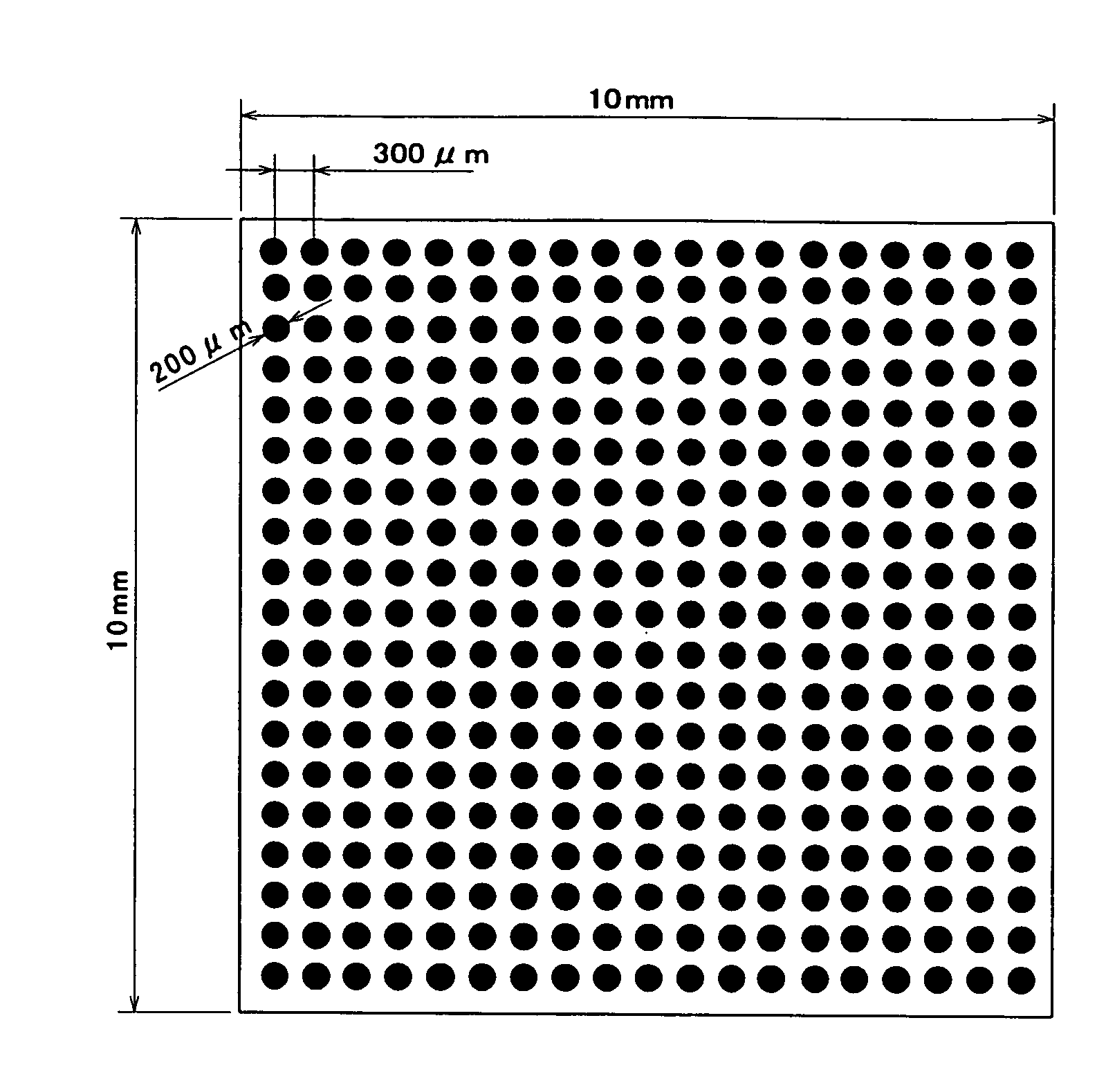
Production of a Graded Refractive Index Microlens Array

[0080]Using a glass of 54 wt. % of SiO2, 22 wt. % of B2O3, 12 wt. % of the total weight of Li2O, Na2O and K2O, 10 wt. % of Al2O3, and 2 wt. % of ZnO as a substrate (10 mm long×10 mm wide×3 mm thick), a graded refractive index microlens array was formed according to the following method.

[0081]The glass substrate was first washed and then a paste of 25% by weight of AgNO3, 40% by weight of NaNO3, 15% by weight of acrylic resin, 15% by weight of cellulose resin, and 5% by weight of terpineol (the paste being prepared by mixing 20 parts by weight of organic solvent, 120 parts by weight of resin component, and 160 parts by weight of additive per 100 parts by weight of silver compound) was applied dropwise using a dispensing pipette to one side of the glass substrate to form 20 by 20 circles (diameter: 200 μm, total 400 dots) with a patterning interval (distance from the center of one circle to the center of the adjacent circle) of 30...


PUM

PropertyMeasurementUnit
Percent by massaaaaaaaaaa
Temperatureaaaaaaaaaa
Weightaaaaaaaaaa

Abstract

The present invention provides a method of producing an optical element without the need for high vacuum, unlike the thin film deposition methods, and without using a molten salt. More specifically, the invention provides a method of producing an optical element comprising applying a paste containing at least one compound selected from lithium compounds, potassium compounds, rubidium compounds, cesium compounds, silver compounds, and thallium compounds, an organic resin, and an organic solvent to a glass substrate containing an alkali metal component as a glass component and then performing heat treatment at a temperature below the softening temperature of the glass substrate.

Description

TECHNICAL FIELD[0001]The present invention relates to a process for producing an optical element, and particularly a process for producing an optical element comprising a glass having a different refractive index region in at least a portion thereof.BACKGROUND ART[0002]In the field of optical communications, optical fiber collimators are conventionally used to emit signal light, which has been transmitted through an optical fiber, in the form of parallel light from the optical fiber, or in reverse, used to converge parallel light on one end surface of an optical fiber to cause the light to enter the optical fiber. When using such an optical fiber collimeter, interposition of an optically functional element (for example, an optical filter, optical isolator, optical switch, optical modulator, etc.) between a pair of collimator lenses can provide a desired effect on the signal light transmitted through a single mode optical fiber at the light-entering side and then converge the signal ...

Claims


Application Information

Patent Timeline
IPC IPC(8): G02B6/10C03C17/00G02B3/00G02B5/18G02B27/10C03C21/00G02B6/132
CPCG02B6/132C03C21/008
Inventor SUETSUGU, TATSUYAKOMINAMI, NORIMASAOHTANI, TAKESHIKAGA, NAOKOYOKOI, HIROAKITAKADA, MINORUTARUMI, TAKASHIEINISHI, TOSHIHIKOKADONO, KOHEI
Owner ISUZU GLASS
Why Eureka
Try Eureka