Metal Evaporation Heating Element and Method for Evaporating Metal

a technology of metal evaporation and heating element, which is applied in the direction of insulation, immersion heating arrangement, borehole/well accessories, etc., can solve the problems of shortened boat life, no evaporation efficiency, and accelerated erosion of the boat by the molten metal

Inactive Publication Date: 2008-10-09
DENKA CO LTD
View PDF6 Cites 12 Cited by
  • Summary
  • Abstract
  • Description
  • Claims
  • Application Information

AI Technical Summary

Problems solved by technology

The boat life greatly relates to wettability of the boat to the molten metal, and if the wettability is poor, not only the molten metal is localized and no evaporation efficiency inherent in the boat will be obtained, but also the progress of erosion of the boat by the molten metal will be accelerated, whereby the boat life will be shortened.
Accordingly, in order to secure the wettability of the boat, various attempts have been made such as irradiation with laser (JP-A-2000-93788), but no sufficient prolongation of life has been achieved.
Further, extensive apparatus and facility will be required for irradiation with laser.

Method used


Image

  • Metal Evaporation Heating Element and Method for Evaporating Metal
  • Metal Evaporation Heating Element and Method for Evaporating Metal
  • Metal Evaporation Heating Element and Method for Evaporating Metal

Examples


example 1

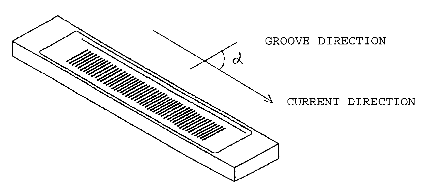
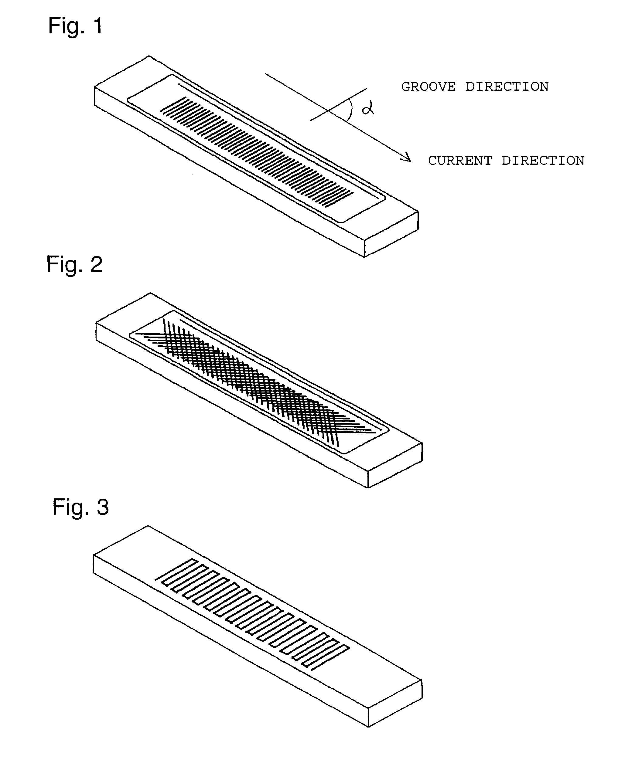
[0063]A material powder mixture comprising 45 mass % of a titanium diboride powder (average particle size: 12 μm), 30 mass % of a boron nitride powder (average particle size: 0.7 μm) and 25 mass % of an aluminum nitride powder (average particle size: 10 μm) was put in a die made of graphite, followed by hot pressing at 1,750° C. to produce a ceramic sintered body (relative density: 94.5%, diameter 200 mm ×height 20 mm). From this ceramic sintered body, a rectangular column having a length of 150 mm, a width of 30 mm and a thickness of 10 mm was cut out, and at a center portion on the upper surface thereof, a cavity having a width of 26 mm, a depth of 1 mm and a length of 120 mm was formed by mechanical processing. On the bottom surface of the cavity, 50 grooves having a width of 1 mm, a depth of 0.15 mm and a length of 20 mm were formed with a distance of 1 mm at an angle of 90° to a current direction by mechanical processing to produce a boat. Its perspective schematic view is show...

example 2

[0064]A boat was produced in the same manner as in Example 1 except that the grooves had a width of 0.5 mm, a depth of 0.1 mm and a length of 20 mm.

example 3

[0065]A boat was produced in the same manner as in Example 1 except that on the bottom surface of the cavity of the boat, 35 grooves having a width of 1 mm, a depth of 0.15 mm and a length of 28 mm were formed with a distance of 1 mm at an angle of 45° to a current direction by mechanical processing, and 35 grooves having the same dimensions were formed at an angle of 135° to the current direction, at right angles to the above grooves by mechanical processing. Its perspective schematic view is shown in FIG. 2.


PUM

PropertyMeasurementUnit
lengthaaaaaaaaaa
depthaaaaaaaaaa
depthaaaaaaaaaa

Abstract

A metal evaporation boat having improved wettability to a molten metal and having a prolonged life, and a method for evaporating a metal employing it.
A metal evaporation heating element characterized by having one or more grooves in a direction not in parallel with a current direction, on an upper surface of a ceramic sintered body comprising titanium diboride (TiB2) and/or zirconium diboride (ZrB2), and boron nitride (BN). It is preferred that the direction not in parallel with the current collection is from 20 to 160° C. to the current direction, that the ceramic sintered body has a cavity and the groove is formed on the bottom surface thereof, and that a predetermined pattern is drawn by a plurality of grooves on the upper surface of the ceramic sintered body and/or on the upper surface of the cavity. In addition, a method for evaporating a metal characterized by using the metal evaporation heating element and heating a metal in vacuum in a state where part or whole of the groove is in contact with the metal.

Description

TECHNICAL FIELD[0001]The present invention relates to a metal evaporation heating element and a method for evaporating a metal.BACKGROUND ART[0002]Heretofore, as a metal evaporation heating element (hereinafter sometimes referred to as “boat”), for example, an electrically conductive ceramic sintered body comprising boron nitride (EN), aluminum nitride (AlN) and titanium diboride (TiB2) as the main components and having a cavity formed on the upper surface thereof has been known (JP-B-53-20256). As one example of commercial products, “BN COMPOSITE EC”, tradename, manufactured by Denki Kagaku Kogyo Kabushiki Kaisha may be mentioned.[0003]As a method of using the boat, each end of the boat is connected to an electrode by a clamp, a voltage is applied to generate heat, and a metal such as an Al wire rod put in the cavity is melted and evaporated to obtain a deposited film, followed by cooling. Such an operation is repeatedly carried out, during which the boat undergoes temperature cycl...

Claims


Application Information

Patent Timeline
Patent Type & Authority Applications(United States)
IPC IPC(8): C23C16/00H05B3/02C23C14/24H05B3/14
CPCC23C14/243H05B3/141C23C14/0641C23C14/0647
Inventor IKARASHI, KOUKIMIYAI, AKIRAWATANABE, SHOUJIROSUSAKI, JUNICHIIWAMOTO, KENTARO
Owner DENKA CO LTD
Why Eureka
Try Eureka