Compact underwater electromagnetic measurement system

Active Publication Date: 2008-10-09
QUASAR FEDERAL SYST
View PDF29 Cites 70 Cited by
  • Summary
  • Abstract
  • Description
  • Claims
  • Application Information

AI Technical Summary

Benefits of technology

[0015]It is an object of the present invention to provide an electromagnetic measurement system that is much more compact, and easier to use than systems used in the prior art. A preferred embodiment of the present invention is directed to a system fo

Problems solved by technology

The result is a cumbersome system with sensing arms than span 10 meters and sensors that must be installed into the system on the deck of a ship, just prior to deployment.
Putting together so sensitive a system on the deck of a ship is a difficult task that reduces the overall reliability of the measurement system when deployed.
In particular, there are a number of discrete modules interfaced by connectors that have the potential to leak and be exposed to seawater, thereby raising the risk of corrosion potentials in the sensing circuit, and in general there is a risk of damaging connector pins.
The fundamental limitation in present underwater electrodes is their requirement to exchange ions with the seawater in order to provide a real (i.e. DC) electrical current path between a first stage amplifier and the ocean.
These chemical reactions and associated diffusion-driven effects mean that resistively coupled electrodes have an inherent settling time and associated level of low frequency electrical noise.
Small variations in this DC potential due to effects such as temperature changes or variations in the local chemical environment (e.g. salinity) lead to an increase in the electrode measurement noise at low frequency.
In a shallow water

Method used


Image

  • Compact underwater electromagnetic measurement system
  • Compact underwater electromagnetic measurement system
  • Compact underwater electromagnetic measurement system

Examples


Embodiment Construction

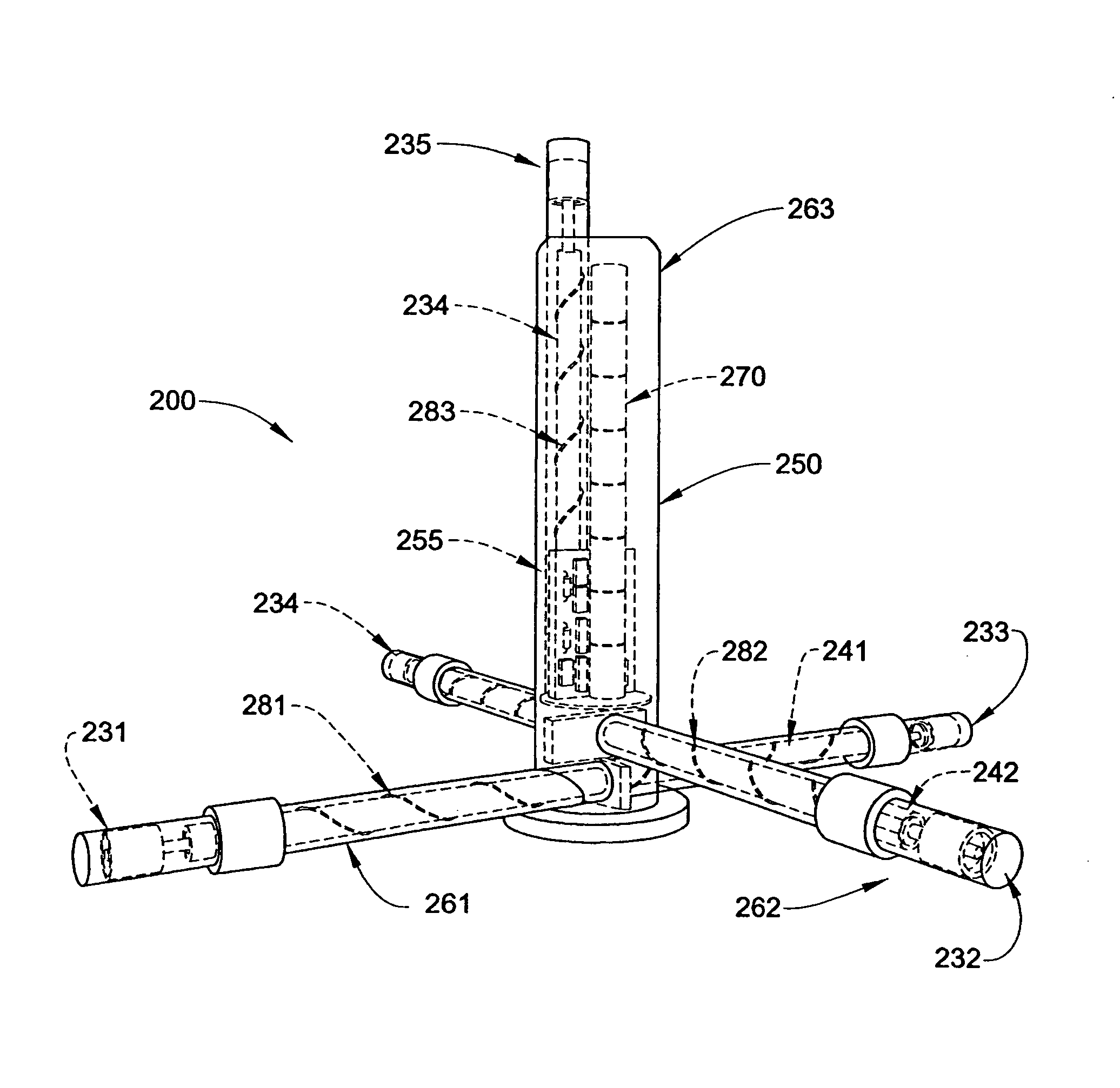
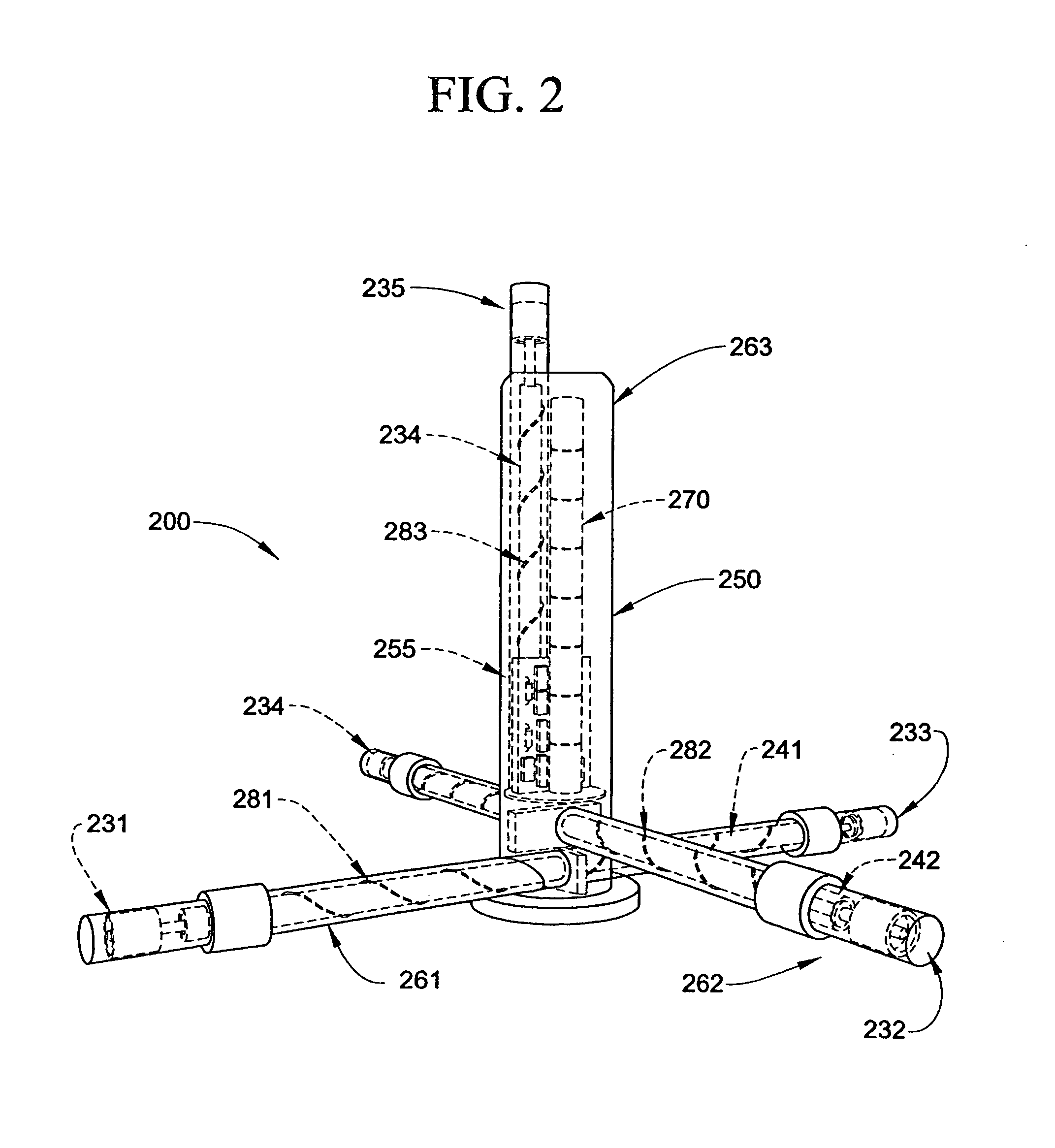
[0041]With initial reference to FIG. 2, a sensor package 200 for measuring electric and magnetic fields comprises a compact arrangement of electric potential antennas 231-235 and magnetic induction coils 241-243 integrated in a single pressure vessel 250. A data acquisition system 255 to record and save sensor data and a power supply 270 are also housed within pressure vessel 250. Pressure vessel 250 is comprised of discrete connected compartments 261, 262, 263 to minimize size and weight. All electrical connections to and between the antennas 231-235, coils 241-243 and data acquisition system 255 are enclosed within pressure vessel 250. All electrical components remain connected at all times. In particular, antennas 231-235, coils 241-243 and other electrical systems are never disconnected from data acquisition system 255 of system 200 during normal operation.

[0042]The single integrated form of pressure vessel 250 enables the magnetic field induction coils 241, 242 to be configured...


PUM


Abstract

An underwater EM measurement system, which is substantially smaller, much simpler to use, and more robust than prior systems, is formed as a sensor package integrated into a single pressure vessel includes two magnetic sensors including induction coils disposed substantially horizontally so as to measure fields in orthogonal directions. The package also includes two electric field sensors including electric potential antennas adapted to couple to a water potential via a capacitive electrode having a conducting material and an electrically insulative layer formed of an insulating material. The capacitive electrode has a capacitance to the medium of greater than 1 mF. Preferably, the insulating material is a metal oxide.

Description

CROSS-REFERENCE TO RELATED APPLICATIONS[0001]The present application claims the benefit of U.S. Provisional Patent Application Ser. No. 60 / 874,184 entitled “Use of Capacitive Electrodes for Underwater Electric Field Measurement” filed Dec. 11, 2006.STATEMENT REGARDING FEDERALLY SPONSORED RESEARCH OR DEVELOPMENT[0002]The U.S. Government has a paid-up license in this invention and the right in limited circumstances to require the patent owner to license others on reasonable terms as provided for by the terms of Navy SBIR Phase I: N68335-05-C-0242 and Navy SBIR Phase II: N68335-07-C-0235.BACKGROUND OF THE INVENTION[0003]The present invention pertains to the art of measuring electric and magnetic fields in a conducting medium. In particular, the invention applies to a system and method to determine the electrical resistivity of the seafloor, and most particularly to offshore hydrocarbon exploration.[0004]Various techniques require measurement of electric and magnetic fields underwater a...

Claims


Application Information

Patent Timeline
IPC IPC(8): G01V3/10
CPCG01R33/04G01R33/10G01R33/12H03F2203/45138G01V3/12G01R29/0871H03F2200/261G01V3/083Y02A90/30G01V3/02G01V3/08
Inventor HIBBS, ANDREW D.NIELSEN, THOMAS KURT
Owner QUASAR FEDERAL SYST
Why Eureka
Try Eureka