Q-switched microlaser apparatus and method for use

a micro-laser and micro-switched technology, which is applied in the direction of laser cooling arrangements, electrical devices, laser details, etc., can solve the problems of limiting the maximum average pump power and output power of the device to levels below those desired for some applications, and occurrence of optical damage, etc., to achieve improved heat removal, reliable operation, and higher pulse repetition rate

Active Publication Date: 2008-10-09
KK TOPCON +1
View PDF10 Cites 54 Cited by
  • Summary
  • Abstract
  • Description
  • Claims
  • Application Information

AI Technical Summary

Benefits of technology

[0018]Passively Q-switched microlasers require improved heat removal to allow them to be reliably operated at higher average powers, which generally means higher pulse repetition rates, without causing thermal stress induced fracture of the laser gain medium or saturable absorber, which would result in catastrophic failure of the laser.
[0019]A reliable method for heat removal from a passively Q-switched monolithic microlaser without significantly impairing its inherent laser performance characteristics is presented. In an embodiment, a passively Q-switched laser apparatus comprises an optically transparent heat conductive element that may be bonded to a gain medium, which in turn may be bonded to a saturable absorber. The saturable absorber may also be bonded to a second optically transparent heat conductive element. Only the gain medium and saturable absorber are disposed within a resonant cavity formed by optical coatings located in the bond interfaces. The gain medium, saturable absorber and laser resonator optical coatings, or mirrors, form a passively Q-switched microlaser, which when longitudinally optically pumped with a suitable source of light will emit high peak power optical pulses. The optically transparent heat conductive element, or elements, serve to efficiently conduct heat from the optical beam path of the microlaser resonator without interfering with the pump light or the microlaser beam paths. In particular, because the optically transparent heat conductive elements lie outside the microlaser resonator they do not add to the resonator optical path length.
[0020]An advantage of the embodiment is to allow higher optical pump powers to be used to provide access to a larger range of pulse repetition rates, which is particularly useful in applications that require the collection of many individual single pulse data. For example, in ranging or range imaging applications. Higher pump powers enable the generation of higher pulse repetition rates because the pump energy required to generate a single Q-switched microlaser pulse is essentially fixed and is therefore delivered in a shorter time at higher pump powers.
[0021]Another advantage of the embodiment is that the use of a heat spreader arrangement leads to significantly reduced thermal lensing and optical distortion in the gain medium and saturable absorber elements thereby improving the output beam quality of the microlaser, especially at higher pump powers. This characteristic is particularly important when using glass host media because of their relatively poor thermal conductivity.
[0022]Another advantage of the embodiment is that the optically transparent heat conductive element may be chosen to specifically transmit either the pump light wavelength or the microlaser output wavelength, while absorbing the other as a means to prevent unwanted pump light from reaching the output beam path or to prevent microlaser pulse energy from reaching and possibly damaging the pump light source, which is typically a semiconductor diode laser.

Problems solved by technology

The single crystal material microlasers may be optically pumped at powers up to several Watts, which may result in the occurrence of optical damage.
The optical damage may be in the form of either bulk crystal fracture or optical coating failure as a result of thermally induced stress lowering the coating damage threshold.
However, some applications require passively Q-switched microlasers to operate with higher pump powers than is possible in a simple device without improved heat removal.
The lack of more direct heat removal from the optically active pumped face of the gain medium, and to a lesser extent the microlaser output face of the saturable absorber, can limit the maximum average pump power and output power of the device to levels below those desired for some applications.
The power limiting mechanism is catastrophic thermal fracture of the materials that constitute the laser because of excessive thermally induced stress.
The problem of thermally induced fracture is worse when using glass materials for the gain medium or saturable absorber.
The pump power limitation is due to the much lower thermal conductivity of the phosphate glass host, 0.85 Wm−1K−1, compared to a typical crystalline host, such as YAG, 13 Wm−1K−1.

Method used


Image

  • Q-switched microlaser apparatus and method for use
  • Q-switched microlaser apparatus and method for use
  • Q-switched microlaser apparatus and method for use

Examples


Embodiment Construction

[0038]A description of example embodiments of the invention follows.

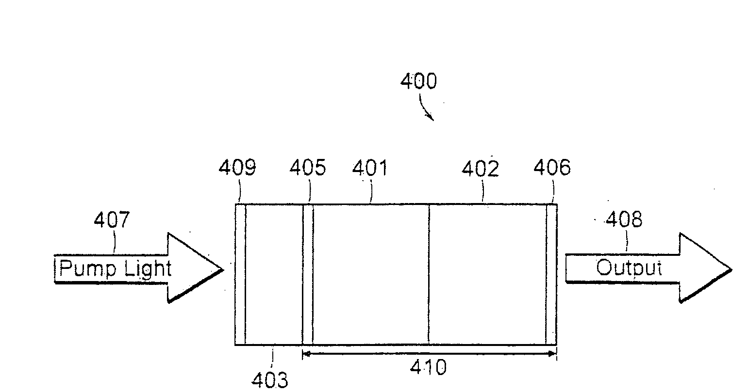
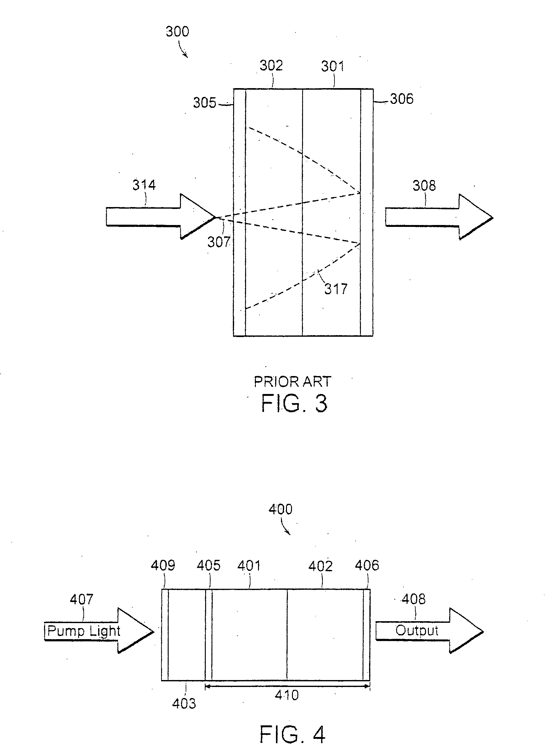
[0039]An apparatus and method for heat removal from a passively Q-switched monolithic microlaser without significantly impairing its inherent laser performance characteristics is presented. The apparatus may comprise an optically transparent heat conductive element that may be bonded to a gain medium, which in turn may be bonded to a saturable absorber. The saturable absorber may also be bonded to a second optically transparent heat conductive element. Only the gain medium and saturable absorber are disposed within a resonant cavity formed by optical coatings located in the bond interfaces.

[0040]The optically transparent heat conductive element, or elements, serve to efficiently conduct heat from the optical beam path of the microlaser resonator without interfering with the pump light or the microlaser beam paths. In particular, because the optically transparent heat conductive elements lie outside the microlaser re...


PUM


Abstract

A monolithic passively Q switched microlaser includes an optically transparent heat conductive element bonded to a gain medium, which is in turn bonded to a saturable absorber, which may also be bonded to a second optically transparent heat conductive element. Only the gain medium and saturable absorber are disposed within the laser resonator.

Description

BACKGROUND OF THE INVENTION[0001]The process of Q-switching involves the introduction of loss, for example with the use of an absorber or shutter, in a laser oscillator sufficient to prevent lasing while energy is being transferred to a gain medium. When the loss is removed, an intense photon flux builds exponentially from spontaneous emission and the coupling of these photons through a partially reflecting resonator mirror leads to the generation of a Q-switched laser pulse. The first report of short intense pulses of laser light, called giant pulses at the time, was from an actively Q-switched ruby laser [McClung, F. J. and Hellwarth, R. W.: “Giant Optical Pulsations from Ruby,”Journal of Applied Physics 33 3, 828-829 (1962)]. Shortly thereafter, passive Q-switching using an organic dye as a saturable absorber was reported [P. P. Sorokin, J. J. Luzzi, J. R. Lenkard and G. D. Pettit: “Ruby Laser Q-Switching Elements using Phthalocyanine Molecules in Solution,”IBM J, vol. 8, pp. 182...

Claims


Application Information

Patent Timeline
Patent Type & Authority Applications(United States)
IPC IPC(8): H01S3/11
CPCH01S3/0405H01S3/042H01S3/0627H01S3/08072H01S3/09415H01S3/1115H01S3/113
Inventor WELFORD, DAVID
Owner KK TOPCON
Why Eureka
Try Eureka