Self Cleaning Aquarium System

Inactive Publication Date: 2008-10-16
GRAD ANDREW
View PDF22 Cites 9 Cited by
  • Summary
  • Abstract
  • Description
  • Claims
  • Application Information

AI Technical Summary

Benefits of technology

[0039]The present invention provides 1) greater ratio of viewing area to water volume; 2) enhanced viewing experience watching fish interact in a more natural, frequently moving environment; 3) the ability to view fish from the unusual perspectives of from the top down, from the bottom up, and from end to end; 4) simplicity of design, requiring only one moving part: the impeller inside a single water pump; 5) an uncluttered aquarium design, as equipment such as filters and heaters are set up in the reservoir which can be hidden from view; 6) lower operating costs, as only a single pump is required, and the filters in the reservoir are engaged by downward water flow when the aquarium periodically drains by gravity; 7) a greatly increased number of fish that can be well-maintained therein compared to any other aq

Problems solved by technology

Modern aquariums do an inadequate job mimicking the environment of stream and river-dwelling fish.
It is difficult and expensive to mimic a coastal reef environment in any commercially available aquarium.
Moreover, no low-cost, simple-to-operate and maintain, and energy efficient aquarium is available that replicates a coastal environment replete with waves and sandy shore.
By the fall of 2001 I had a functioning tubular aquarium, but I could not find simple solutions to several aspects of maintaining a healthy environment.
For example, while I could easily introduce fish to the aquarium, I could not easily remove a fish without dismantling much of the prototype.
These air bubbles interfere with water flow and are difficult to remove.
When I examined the drawings and specifications, I saw that my tubular aquarium was a substantial improvement in simplicity and functionality, yet my design at the time was still too impractical for sale.
There is no portion of the aquarium in which unhealthy microorganisms can reproduce in stagnant water.
Cleaning aquariums is an unpleasant chore for most aquarium owners.
Aquarium filters cannot remove all of the waste and debris, and thus periodic aquarium cleanings are required.
All, except U.S. Pat. No. 5,849,185 issued to Judy, are relatively expensive to manufacture.
In addition, it substantially reduces the viewing area of the aquarium.
Because commercially sold aquariums do not provide for automatic and frequent exchange of large volumes of water, waste is left trapped in corners and close to the surface.
None of the above referenced prior art removes waste and debris floating in the water unless it is already very near the bottom of the aquarium.
Referring again to U.S. Pat. No. 5,605,115 issued to Dale, such a device is far from an ideal environment for keeping fish.
For example, there is no simple way

Method used


Image

  • Self Cleaning Aquarium System
  • Self Cleaning Aquarium System
  • Self Cleaning Aquarium System

Examples


first embodiment

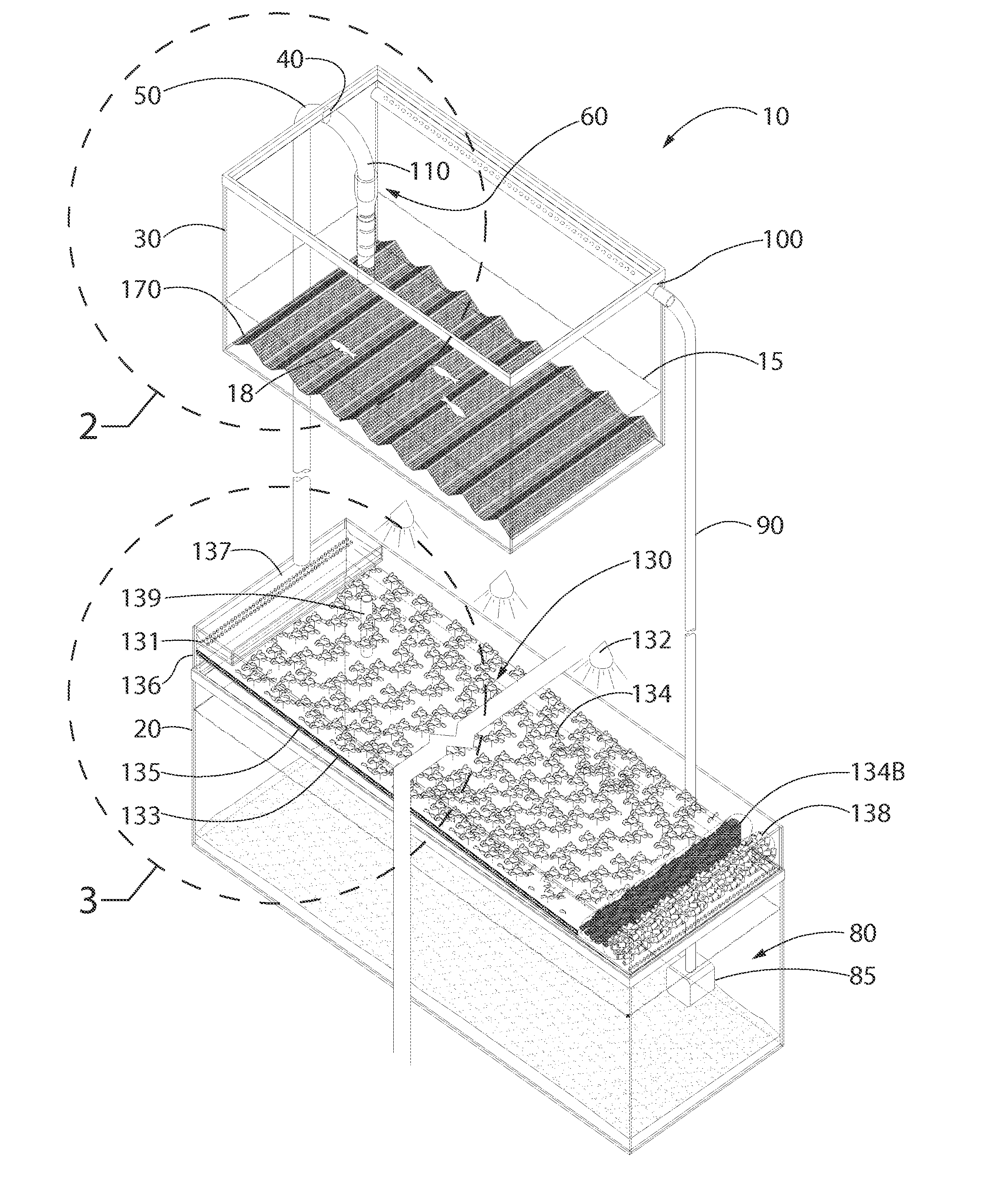
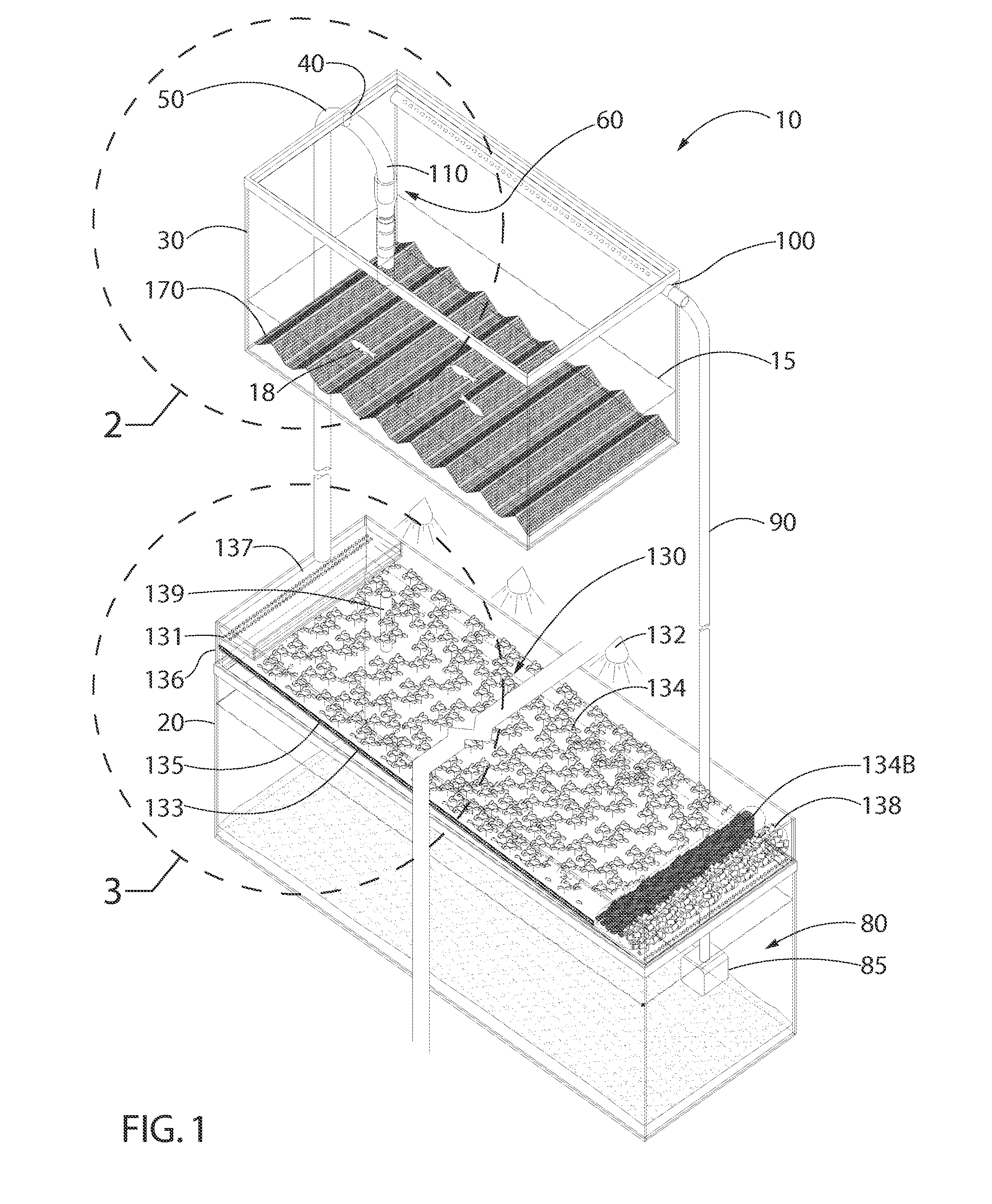
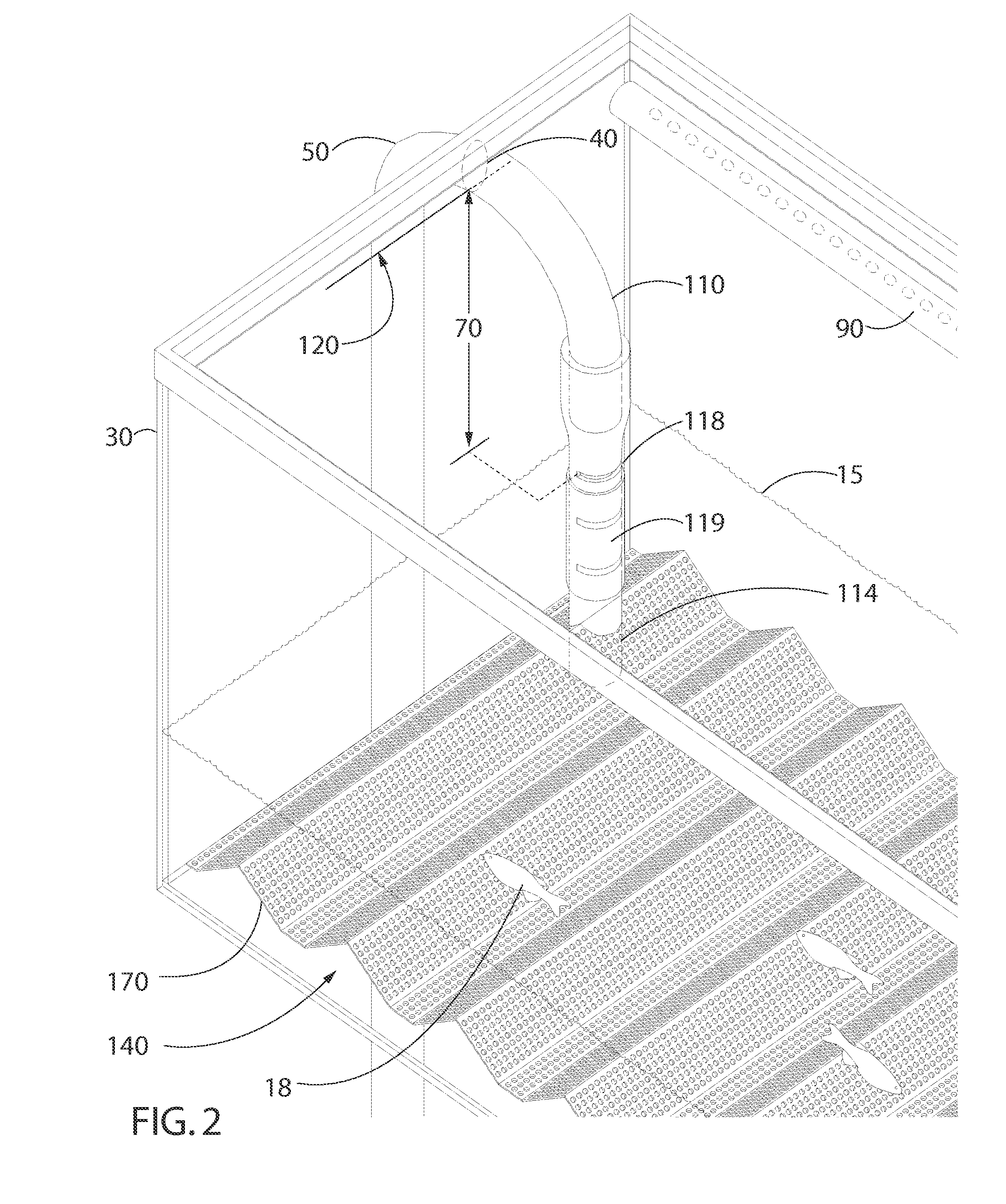
[0048]FIGS. 1-3 illustrate an aquarium system 10 for containing water 15 and aquatic life 18 therein. The aquarium system 10 includes a reservoir 20 and an aquarium 30 that is mounted generally above the reservoir 20. The aquarium 30 and the reservoir 20 may be mounted together as part of the same unit (not shown), or separately mounted, provided that the aquarium 30 is fixed generally above the reservoir 20 so as to allow siphoning of the water 15 from the aquarium 30 to the reservoir 20 as described in more detail below. The aquarium 30 and the reservoir 20 are both capable of water-tight containment of liquids, and can be formed in any desired shape and of any suitable material, such as acrylic, polycarbonate, glass, plastic (either opaque, translucent or transparent, as desired), or the like.

[0049]The aquarium 30 has an outlet 40 in liquid communication with the reservoir 20 through an outlet conduit 50. The outlet 40 is located at a maximum water level 120 inside the aquarium 3...

second embodiment

[0056]In the invention, illustrated in FIGS. 4-6, the aquarium 30 takes the shape of an elongated, substantially transparent tube 150, preferably having at least one opening at a top side thereof that includes a removable cover 156 (FIG. 4 and FIG. 7). The tube 150 may preferably include a circular cross-section, as illustrated, but may include any other cross-sectional shape including square, oval, teardrop, rectangular, irregular, trapezoidal, or the like. Further, such a tube 150 may be formed in the shape of a U-shaped or V-shaped trough with an open top end (not shown), and may or may not have a linear longitudinal axis. In such an embodiment, the aquarium 30 may be mounted non-horizontally such that the outlet 40 is positioned proximate a lower end 24 of the aquarium 30. As such, water 15 flows generally from the inlet 100 to the outlet 40 through the tube 150, creating a river-like current through the tube 150 that emulates natural water flow conditions for the aquatic life 1...


PUM


Abstract

An aquarium system for containing water and aquatic life therein is disclosed that includes a reservoir and an aquarium that is mounted generally above the reservoir. The aquarium has an outlet in liquid communication with the reservoir through an outlet conduit that includes a discharge means, preferably an inverted U-shaped siphon conduit, that periodically discharges a portion of the water from the aquarium to the reservoir therethrough once the water has reached a maximum water level. A pumping means pumps water from the reservoir up to the aquarium through an inlet conduit that is in fluid communication with the reservoir and an inlet of the aquarium. As such, when the water reaches the maximum level in the aquarium, the siphon conduit substantially fills with water which begins to flow out through the outlet conduit, drawing a portion of water from the aquarium rapidly through the outlet conduit until the water in the aquarium reaches the open bottom end of the siphon conduit. Air in the aquarium thereafter enters the siphon conduit to break the siphon. Water leaving the output conduit enters a filter means to filter and clean the water before it is returned to the aquarium by the pump. An embodiment emulating the current of a river, wherein the aquarium takes the shape of an elongated, substantially transparent tube or trough, is further disclosed. A wave surge means may be included for producing periodic wave surges in the aquarium.

Description

CROSS-REFERENCE TO RELATED APPLICATIONS[0001]This application claims the benefit of U.S. Provisional Patent Application 60 / 851,209, filed on Oct. 12, 2006, and incorporated herein by reference.STATEMENT REGARDING FEDERALLY SPONSORED RESEARCH AND DEVELOPMENT[0002]Not Applicable.FIELD OF THE INVENTION[0003]This invention relates to fish aquariums, and more particularly to a self-cleaning aquarium that emulates natural water flows for aquatic life.BACKGROUND AND DISCUSSION OF RELATED ART[0004]Displaying fish in an aquarium has been a popular hobby throughout the world for hundreds of years. The first glass aquariums were constructed in the 1800's. Since that time the basic design of the fish aquarium has changed little. Fish are to this day kept most frequently in a tank of water which has a relatively small viewing area in relation to the volume of water contained therein. Aquariums are almost always illuminated from above, which prevents viewing the fish from above, which is how fish...

Claims


Application Information

Patent Timeline
IPC IPC(8): A01K63/04
CPCA01K63/003A01K63/04A01K63/045A01K63/047
Inventor GRAD, ANDREW
Owner GRAD ANDREW
Why Eureka
Try Eureka