
Composite Articles Comprising Protective Sheets and Related Methods

a technology of protective sheets and composite articles, applied in the field of composite articles, can solve the problems of composite articles being susceptible to interlayer delamination, compromising the structural integrity of such articles, and compromising the strength or stiffness of the associated material,

Active Publication Date: 2008-10-23
PPG ADVANCED SURFACE TECH LLC
View PDF108 Cites 39 Cited by
  • Summary
  • Abstract
  • Description
  • Claims
  • Application Information

AI Technical Summary

Benefits of technology

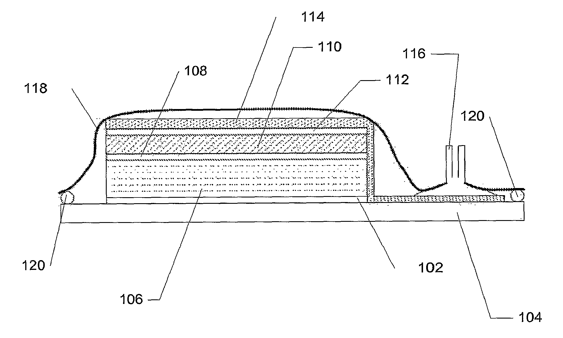
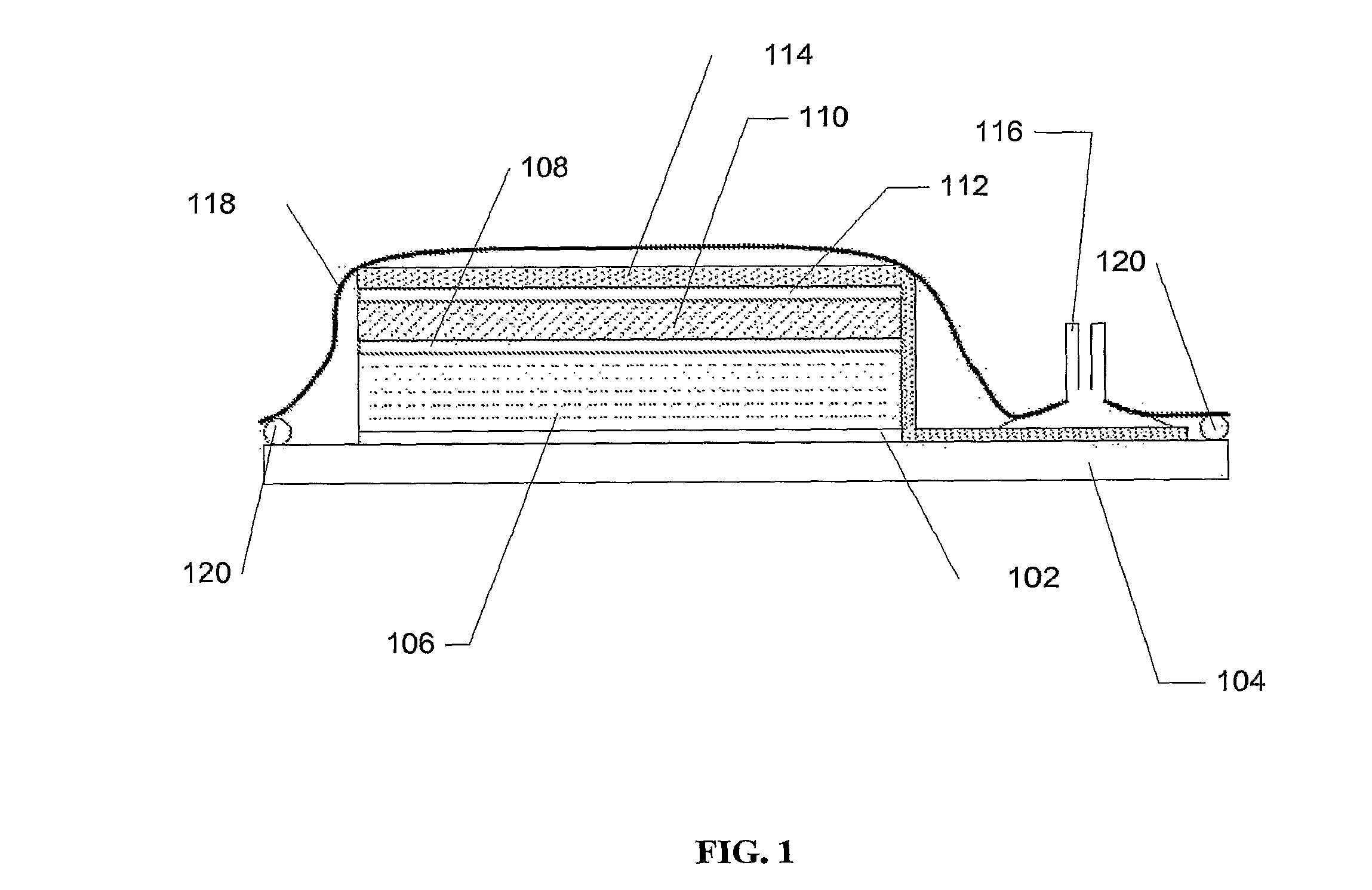
[0022]According to one aspect of the invention, a composite article comprises a protective sheet integrally bonded to at least one portion thereof. According to another aspect of the invention, a composite article comprises an exterior protective sheet adhered to an underlying composite material surface, wherein the composite article is essentially free of additional layers between the protective sheet and the underlying composite material surface. According to yet another aspect of the invention, a composite article comprises a protective sheet adhered to at least one exterior portion thereof, wherein the protective sheet is capable of providing all desired enhancements in performance and aesthetic properties of the composite article in one protective sheet component as compared to use of multiple protective sheet or protective coating components.

Problems solved by technology

Composite materials are finding increased use in applications where lightweight materials are desired and where an associated compromise in strength or stiffness of the material would likely be problematic.
In addition, as many composite articles are made by layering multiple, individual composite material layers to achieve the desired properties, such composite articles are susceptible to interlayer delamination, particularly upon impact.
When interlayer delamination occurs, structural integrity of such articles is compromised, sometimes leaving the composite article useless as intended.
Further, in extreme cases where the composite article fractures, a sharp broken surface can result (i.e., with reinforcing fibers extending haphazardly therefrom), which impacts not only the usefulness of the article, but also the safety of those using such articles and those around them.
In addition, gel coats can provide some, although limited, enhancements in abrasion resistance.
The result is that the surface of the composite article, which is formed against the face of the mold, contains imperfections that can detract from a glass-like appearance otherwise desired.
While gel coats are capable of improving the aesthetics of surfaces to which they are applied, they are often not capable of imparting some or all of the desired performance properties.
For example, gel coats are often too thin or too hard to provide substantial levels of abrasion resistance.
Further, gel coats typically do not provide significant impact resistance when used on composite articles.
After extended use, gel coats also have a tendency to crack, which enables water to penetrate into articles on which they are applied.
Over time, such water penetration may lead to significant structural damage of the composite article.
When the article is subjected to freeze-thaw cycling (e.g., as with many aerospace parts that undergo several freeze-thaw cycles in a single day of operation), premature structural failure is often more rapid, as any water trapped within the composite article will likely produce larger cracks and similar internal damage based on such freeze-thaw cycling.
In addition to their inability to often provide desired performance properties, use of gel coats typically decreases overall processing efficiency.
For example, if the gel coat is spray-applied to a surface in a post-processing step, additional labor and manufacturing time is required in conjunction therewith.
Such cure time can take several hours, which is obviously undesirable from the perspective of processing efficiency.
The types of materials that can be applied as a gel coat are also limited, which is undesirable as it decreases flexibility in design and manufacture of composite articles.
For example, many conventional gel coat materials are two-part compounds having a relatively short pot life, which requires that they be used within a few hours of compounding or discarded.
For example, availability of certain polymer matrix systems for in-mold processing, such as those based on epoxy thermoset resins used with carbon fiber reinforcements, is very limited.
Many undesirable issues can arise, however, if the pressure sensitive adhesive is not adequately designed and formulated.
For example, many pressure sensitive adhesives lack adequate bond strength to prevent edge lifting of protective sheets that are adhered to an underlying surface using the same.
The durability of such constructions is often short-lived, as the adhesive bond often fails during repeated use, causing the protective sheet to lift from the surface.
However, such pressure sensitive adhesives typically lack adequate permanency.
In addition to the shortcomings associated with bonding of protective sheets to an underlying surface, application of protective sheets has proven to be otherwise difficult.
For example, in addition to the bonding issues arising based on the often inadequately extensible nature of conventional protective sheets, it is often difficult to apply protective sheets to surfaces with complex shapes when relatively thick or multi-layer protective sheets are used.
As a result, wrinkles often exist in protective sheets so applied.
Even if uniformly applied to irregular surfaces initially, over time conventional protective sheets are prone to lifting from such surfaces.
In any event, the way in which protective sheets are typically applied to such surfaces generally decreases processing efficiency.
While some benefits can be obtained from application of protective sheets and protective coatings according to known methods, such conventional methods often result in composite articles that still fail to adequately address important performance and processing considerations.
When attempting to address the myriad of important considerations, however, processing efficiency is often compromised.

Method used


Image

  • Composite Articles Comprising Protective Sheets and Related Methods
  • Composite Articles Comprising Protective Sheets and Related Methods

Examples


example 1

[0113]An extensible polyurethane-based protective sheet was prepared such that the sheet comprised a carrier layer having a thickness of 150 microns, a topcoat layer having a thickness of 18 microns, and an adhesive layer having a thickness of 60 microns. The adhesive layer was adhered to the opposite side of the carrier layer from the topcoat layer. A standard release liner was positioned exterior to the adhesive layer, but was removed prior to testing.

[0114]To prepare the sheet, first a 98# polyethylene-coated kraft paper with silicone coated on one side was used as a release liner onto which the adhesive layer was formed. The adhesive layer was formed from an adhesive composition prepared by charging a closed vessel with initial components as follows: 20% by weight 2-ethyl hexyl acrylate, 5% by weight methyl acrylate, 1% by weight acrylic acid, 37% by weight ethyl acetate, 7% by weight isopropyl alcohol, 26.1% by weight toluene, and 3.75% by weight n-propanol. The weight percenta...

examples 2a-2c

[0122]For each fiber-reinforced composite, a woven carbon fiber fabric containing about 3K tow-weight carbon fiber is used. Such fibers and fabric are available from a variety of commercial suppliers, including A&P Technologies (Cincinnati, Ohio), Fabric Development, Inc. (Quakertown, Pa.), and Textile Products, Inc. (Anaheim, Calif.). For each of Examples 2A-2C, a different uncured epoxy resin composition is used to impregnate the woven carbon fiber fabric. Formulation of the epoxy resin composition for each of Examples 2A-2C is described further below.

[0123]After preparation of the epoxy resin composition and hand impregnation of the woven carbon fiber fabric therewith, four layers of the now impregnated “prepreg” carbon fiber fabric are stacked upon one another.

[0124]As an outer layer, a 150-μm (0.006-inch) thick film of a polycaprolactone-based, aliphatic thermoplastic polyurethane film (available from Argotec, Inc. of Greenfield, Mass.) is positioned on top of the four stacked ...

example 3

[0135]Several layers of carbon fiber prepreg were prepared by hand-coating sufficient epoxy thermoset resin into a 12K woven carbon fiber fabric. The epoxy resin formulation was prepared based on 100 phr of EPON 863 (a Bisphenol-F epoxy resin available from Resolution Performance Products of Houston, Tex.), 22.4 phr of Ancamine 2441 (a modified polyamine curing agent available from Air Products and Chemicals, Inc. of Allentown, Pa.), and 5 phr of CAB-O-SIL TS-720 (a treated fumed silica available from Cabot Corporation of Billerica, Mass.). A protective sheet was directly bonded to the resulting epoxy-carbon fiber composite article using in-mold vacuum bag processing. The protective sheet consisted of a 150-μm (0.006-inch) thick film of a polycaprolactone-based, aliphatic thermoplastic polyurethane film (available from Argotec, Inc. of Greenfield, Mass. under the trade designation ARGOTEC 49510).

[0136]A flat aluminum plate was used as a vacuum bag mold surface. Prior to configuring ...


PUM

PropertyMeasurementUnit
Volumeaaaaaaaaaa
Fractionaaaaaaaaaa
Fractionaaaaaaaaaa

Abstract

Methods of the invention include those for applying protective sheets to composite articles. According to these methods and resulting composite articles, a protective sheet is applied to at least a portion of an exterior surface formed from a composite material and where protection is desired. At least one exterior surface of the composite article to be protected can be integrally formed in the presence of the protective sheet. Improved bonding of the protective sheet to the composite article and improved processing efficiency are advantageously achieved according to the invention.

Description

BACKGROUND OF THE INVENTION[0001]The present invention relates generally to composite articles made from composite materials and which comprise protective sheets, as well as methods of making and using the same.[0002]A variety of protective sheets and protective coatings can be selectively applied to protect exterior surfaces on a variety of articles. Often, protective sheets and protective coverings are selectively applied to an article's surface after the article is formed. Many such applications are intended to reduce abrasion or other wear on the underlying surface. Other applications are geared primarily toward maintaining or improving aesthetics or integrity of an underlying surface (e.g., when the underlying surface contains printed material thereon or when the surface contains aesthetically undesirable pinholes, bubbles, or other surface imperfections that can occur when, for example, producing molded articles). It is not surprising that there exists a need for protective sh...

Claims


Application Information

Patent Timeline
IPC IPC(8): B32B27/02
CPCB29C37/0025Y10T428/24364B29C51/28B29C70/086B29C70/44B29C2043/3644B29C2791/006B29K2105/0854B29K2105/243B29L2009/001B29L2031/52B32B27/08B32B27/18B32B27/304B32B27/322B32B27/38B32B27/40B32B2307/4023B32B2307/714B32B2307/752B32B2509/00B32B2603/00B32B2605/18Y10T156/10Y10T428/26Y10T428/239B29C43/12Y10T428/249939Y10T428/31507Y10T428/31551
Inventor MCGUIRE, JAMES E.STRANGE, ANDREW C.
Owner PPG ADVANCED SURFACE TECH LLC
Learn More