Resin-Coated Stainless Steel Foil, Container and Secondary Battery

a stainless steel foil and secondary battery technology, applied in the field of resin-coated stainless steel foil, a container and a secondary battery, can solve the problems of poor corrosion resistance of metal foil in an electrolytic, serious damage to the apparatus where the secondary is located, and risk of liquid leakage of electrolytic solution, etc., to achieve excellent workability, good corrosion resistance, and strong adherence force

Active Publication Date: 2009-01-29
NIPPON STEEL & SUMIKIN MATERIALS CO LTD
View PDF4 Cites 46 Cited by
  • Summary
  • Abstract
  • Description
  • Claims
  • Application Information

AI Technical Summary

Benefits of technology

[0030]According to the present invention, a stainless steel foil capable of maintaining strong adherence force to a film even in an electrolytic solution to exhibit good corrosion resi

Problems solved by technology

However, if the strength of the container is decreased due to thinning, a risk of liquid leakage of the electrolytic solution due to deformation or breakage when an outer force or piercing is applied.
The liquid leakage of the electrolytic solution has a high possibility of causing serious damage to the apparatus where the secondary battery is incorporated.
If the container member is plastic or aluminum, strength is insufficient with a wall thickness of 200 μm or less.
However, the metal foil has poor corrosion resistance in an electrolytic solution and when used for a battery casing or a lead wire, is sometimes eroded by the electrolytic solution.
However, the film sometimes fails to exert sufficiently high adherence when the thickness of the chromate treatment layer is inadequate.
Also, if the chromate treatment layer is thicker than necessary, this is disadvantageous in that a chromate having a large environmental load is uselessly used.
I

Method used

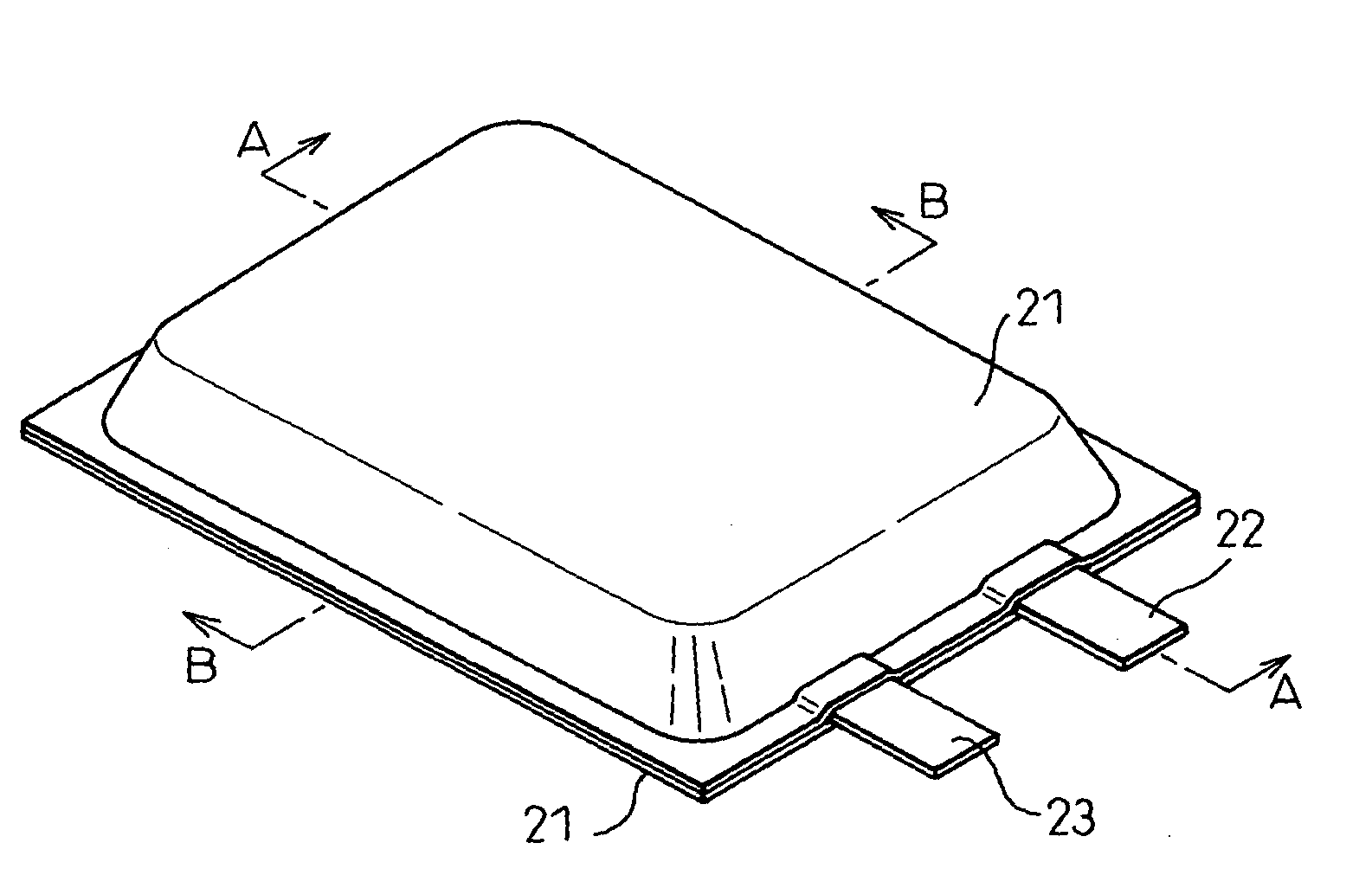
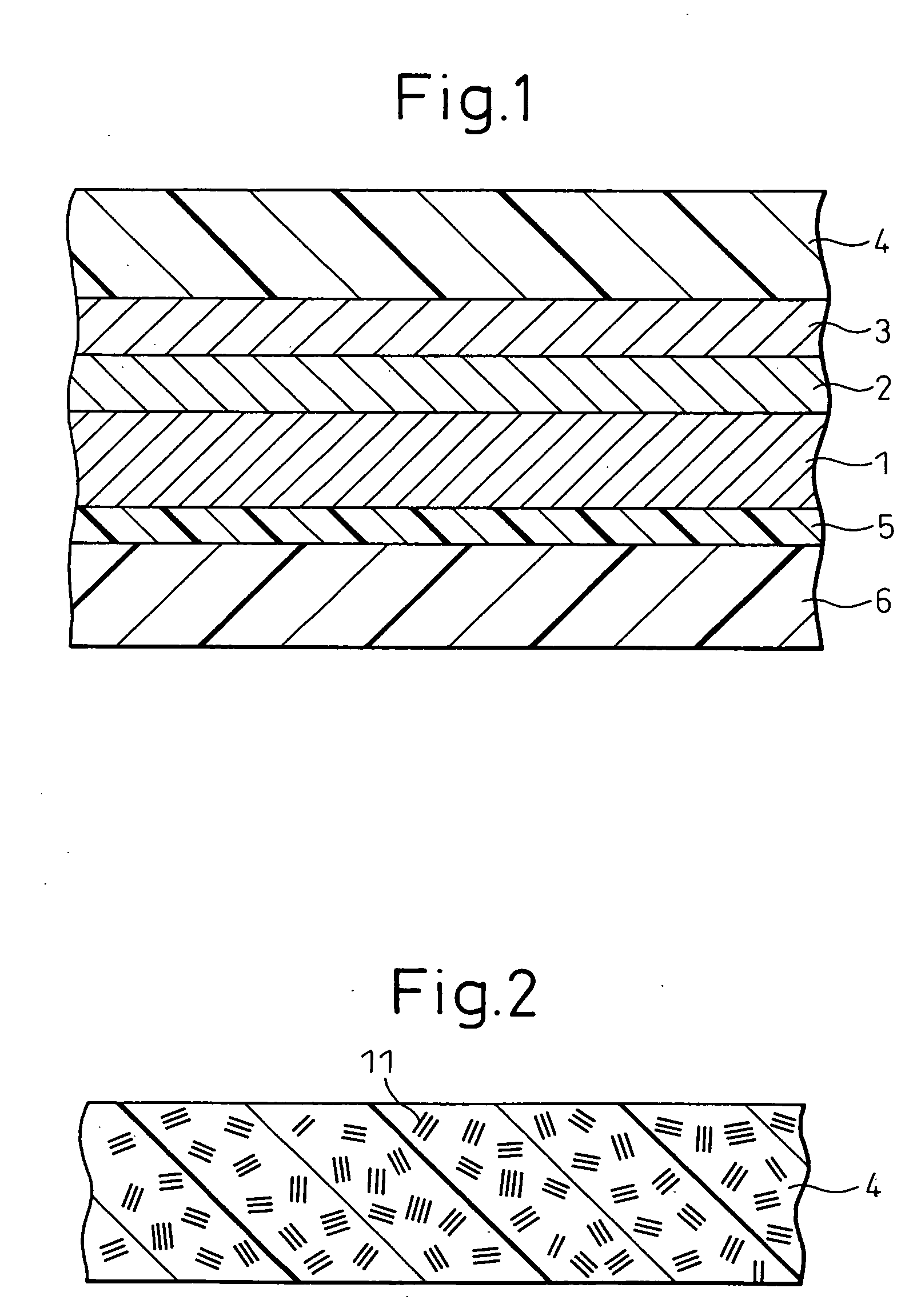
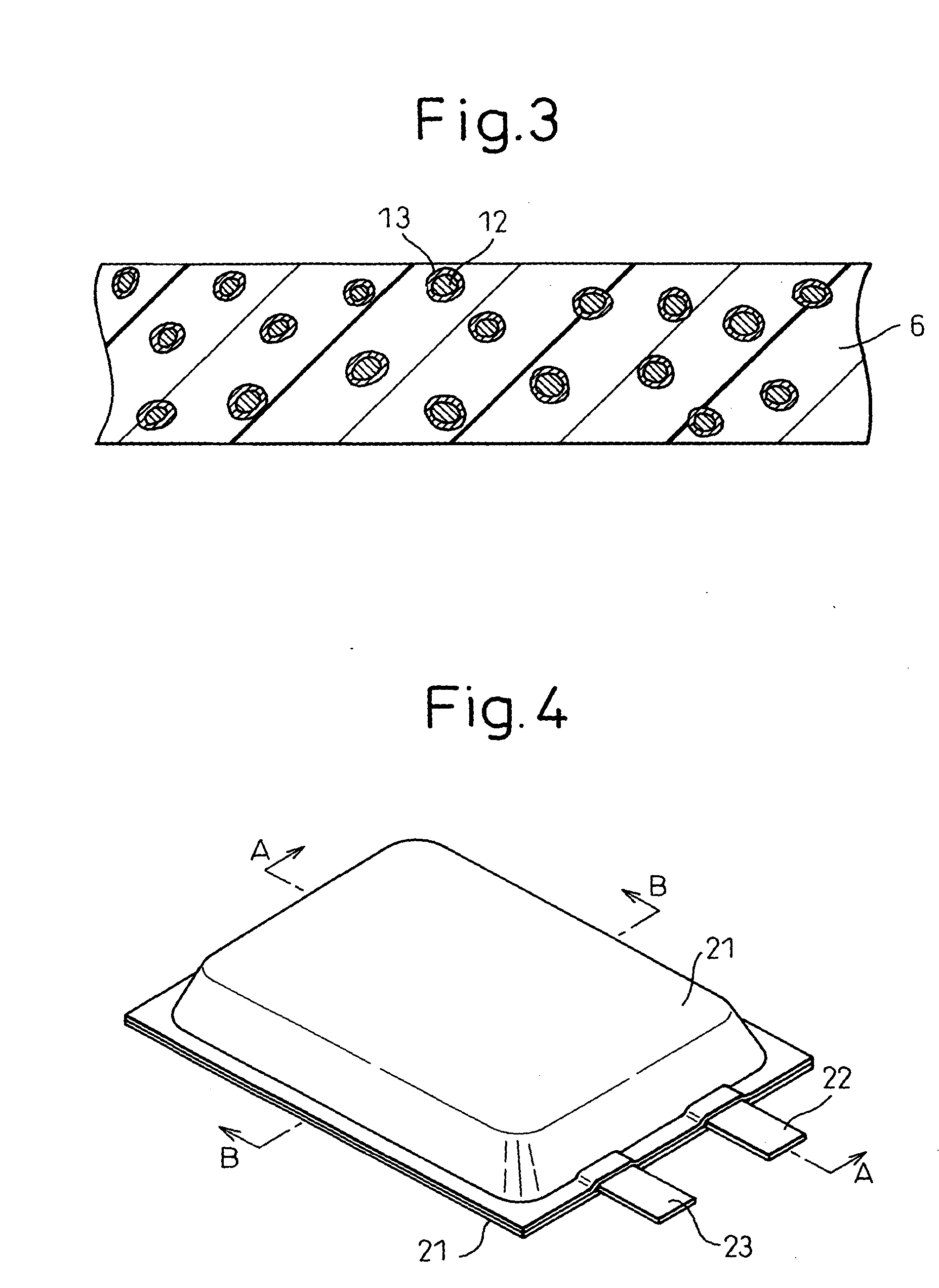

Image

  • Resin-Coated Stainless Steel Foil, Container and Secondary Battery
  • Resin-Coated Stainless Steel Foil, Container and Secondary Battery
  • Resin-Coated Stainless Steel Foil, Container and Secondary Battery

Examples


examples

[0113]The present invention is described in greater detail below by referring to Examples and Comparative Examples, but the present invention is not limited only to these Examples.

examples 1 to 16

[0114]The stainless steel foil used in these Examples was 50 μm-thick SUS316L Bright A produced by Nippon Steel Corp.

[0115]The nickel strike plating in Examples 9 to 16 and Comparative Examples 2 to 4 was performed as follows. The stainless steel foil was subjected to acid pickling in an aqueous 30 mol % sulfuric acid solution, acid pickling in an aqueous 15 mol % hydrochloric acid solution, and nickel strike plating in a bath containing 240 g / L of nickel chloride and 125 mL / L of hydrochloric acid (specific gravity: 1.18), to which electricity at a cathode current density of 5 A / dm2 was passed for 5 seconds. These treatments all were performed at ordinary temperature.

[0116]The chromate treatment was performed using a bath containing 25 g / L of chromium anhydride, 3 g / L of sulfuric acid and 4 g / L of nitric acid, in which phosphoric acid, hydrochloric acid, ammonium fluoride or the like was appropriately added, at a cathode current density of 25 A / dm2 to form a chromate treatment layer...


PUM

PropertyMeasurementUnit
Percent by massaaaaaaaaaa
Thicknessaaaaaaaaaa
Thicknessaaaaaaaaaa

Abstract

The present invention provides a resin-coated stainless steel foil capable of maintaining a strong adherence force to the film even in an electrolytic solution to exhibit good corrosion resistance and excellent in the workability, design property and piecing resistance, and a container and a secondary battery each using the resin-coated stainless steel foil. According to the present invention, a resin-coated stainless steel foil having a chromate treatment layer of 2 to 200 nm in thickness on at least one surface of a stainless steel foil and having at least a polyolefin-based resin (A) layer containing a functional group having polarity on the chromate treatment layer; and a container and a secondary battery each using the resin-coated stainless steel foil are provided.

Description

TECHNICAL FIELD[0001]The present invention relates to a resin-coated stainless steel foil, a container and a secondary battery, which are excellent in corrosion resistance, workability, design property and piercing resistance.BACKGROUND ART[0002]A secondary battery such as a nickel-cadmium battery, nickel-hydrogen battery and lithium ion battery is widely used in electronic devices or components, particularly in cellular phones, notebook personal computers, video cameras, satellites and electric or hybrid cars. Conventionally, in the case of a secondary battery using a strong alkali electrolyte, such as nickel-cadmium and nickel-hydrogen, a casing composed of a nickel-plated cold-rolled steel sheet or a plastic casing has been used. In a battery using a nonaqueous electrolyte, such as a lithium ion battery, the electrolyte incorporated into an aluminum pouch is wrapped with a plastic casing or a casing composed of a nickel-plated steel sheet or stainless steel sheet.[0003]In recent ...

Claims


Application Information

Patent Timeline
IPC IPC(8): H01M2/04B32B15/00H01M50/105H01M50/119H01M50/121H01M50/128H01M50/133H01M50/145
CPCB32B15/08Y10T428/265C25D5/56C25D11/38H01M2/0207H01M2/0275H01M2/0277H01M2/0285H01M2/0287H01M2/0295H01M10/052H01M10/0585H01M10/0587H01M10/24Y02T10/7011Y10T428/13B32B15/18Y02E60/10H01M50/124Y02P70/50H01M50/105H01M50/133H01M50/121H01M50/145H01M50/128H01M50/119C23C22/00B32B15/085
Inventor IBARAGI, MASAHARUKAJIRO, HIROSHIOHISHI, HIROSHI
Owner NIPPON STEEL & SUMIKIN MATERIALS CO LTD
Why Eureka
Try Eureka