

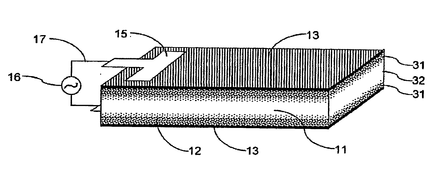
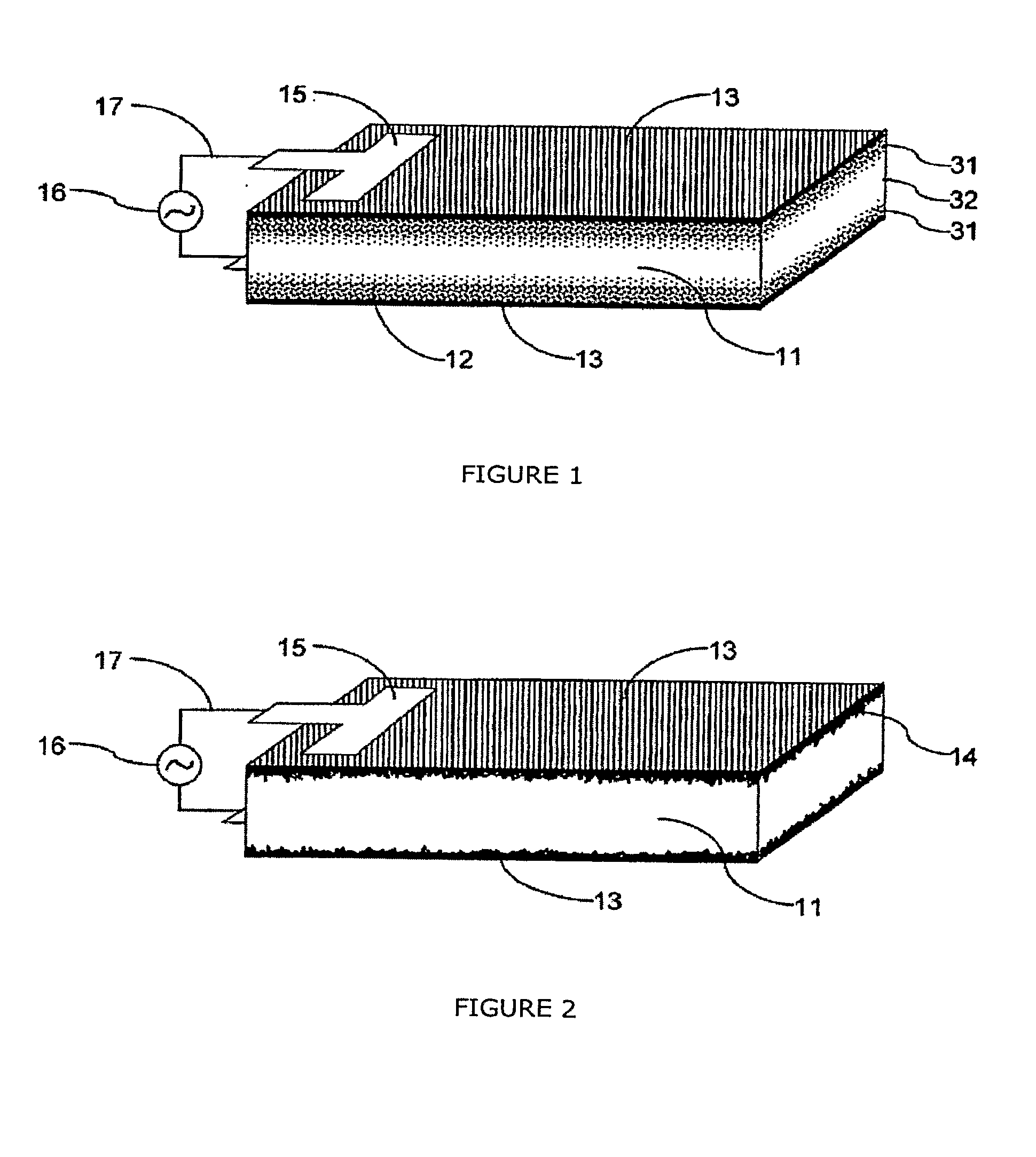
Ionic polymer devices and methods of fabricating the same
a technology of ionic polymer and fabricated devices, which is applied in the direction of instruments, cell components, material electrochemical variables, etc., can solve the problems of deformation or bending of the actuator, the fabricated device requires only modest operating voltage, and the process is long and expensive, so as to improve the actuation performance and sensitivity of the device, improve the electrical capacitance of the ionic polymer device, and the manufacturing process is simple and cheaper. the effect of speeding up
- Summary
- Abstract
- Description
- Claims
- Application Information
AI Technical Summary
Benefits of technology
Problems solved by technology
Method used
Image

Examples
example 1
Nafion-Au Actuator Via Two-Time in-situ Reduction Method
[0084]2 mL of 5% Nafion alcohol solution was mixed with 1 ml of 10 mg / mL HAuCl4 aqueous solution and then cured at an elevated temperate (about 80° C.) and moderate vacuum (about 5 inHg rel.) in a Teflon beaker. When the mixture becomes viscous, uniformly add 0.5 mL of 5 mg / mL NaBH4 aqueous solution as a reducing agent from the second surface. A micro-sprayer may also be used to apply the reducing agent to ensure the small size and uniformity of the droplets. Alternatively, 0.5 ml of 25 mg / mL sodium citrate aqueous solution can be added as a reducing agent. The reduced gold nanoparticles then precipitated toward a first surface due to the gravitation, and a concentration profile was formed in the Nafion polymer matrix at and near the first surface.
[0085]When the mixture becomes even more viscous, another portion of the reducing agent is introduced from the second surface. Since the higher viscosity made it harder for the nanopa...
example 2
Nafion-Au Actuator Via One-Time in-situ Reduction and Layer Bonding
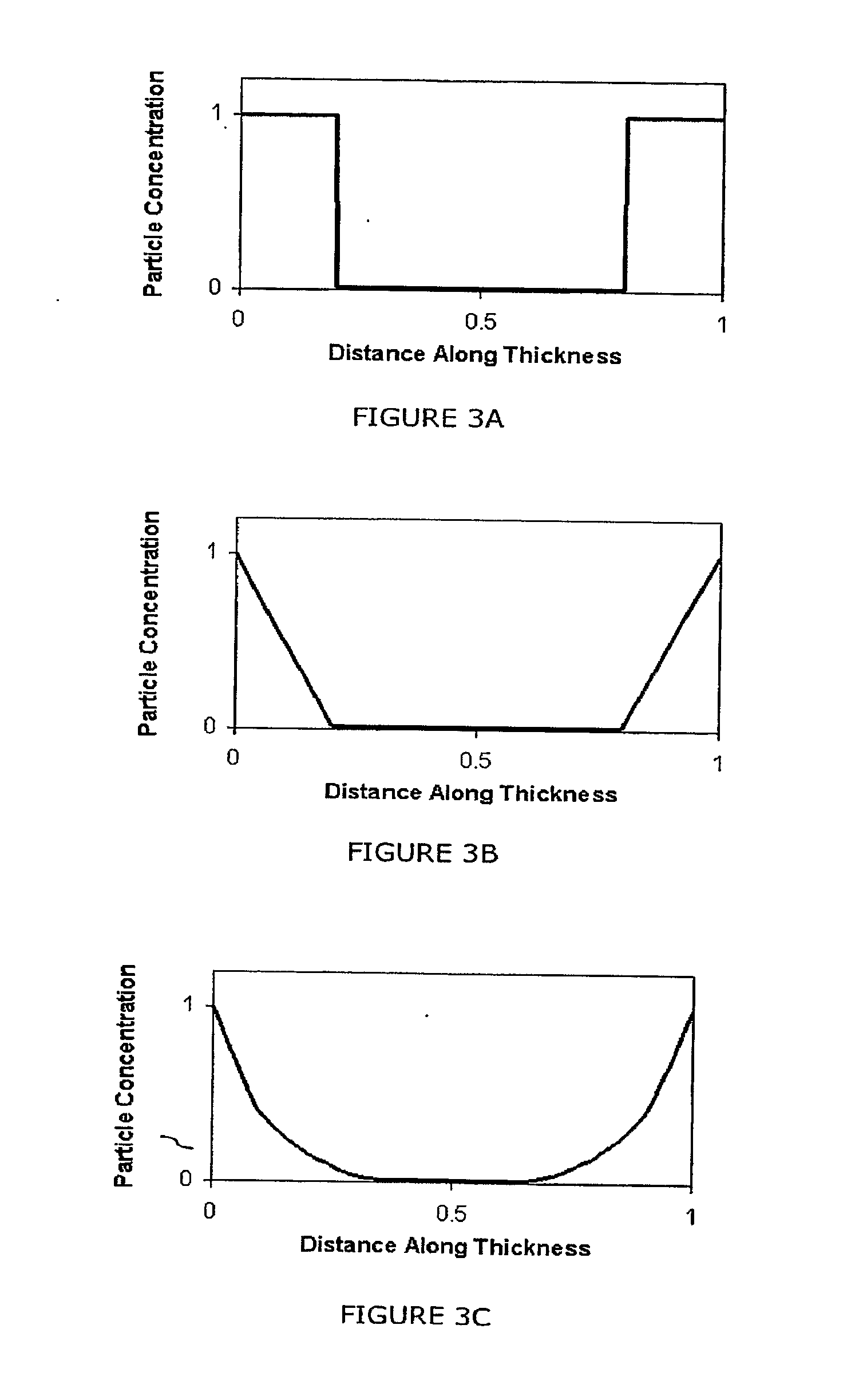
[0088]3 mL of 5% Nafion solution, 1.5 mL of DMF and 2 mL of 10 mg / mL HAuCl4 solution were mixed together and cured at an elevated temperate (about 80° C.) and moderate vacuum (about 5 inHg rel.) in a Teflon beaker. 3 mL of 25 mg / mL sodium citrate was added from the second surface when the polymer membrane becomes viscous. After the polymer was completely cured, its cross section was characterized using SEM and energy dispersive X-ray scanning (EDS). A SEM image of the cross-section of the extended electrode layer near the first surface shows that well-dispersed gold nanoparticles of about 50 nm are present near the first surface in the Nafion polymer matrix. FIG. 13 is an EDS analysis result showing the concentration gradient profile of the Au nanoparticles along the extended electrode layer thickness. The gold nanoparticles were more concentrated at and toward the first surface, with gradually decreasing concentrati...
example 3
Nafion-Ag Actuator Via Preformed Conductive Particle Dispersion
[0090]Preformed silver nano-powder (SNP) with an average diameter of the particle size less than 100 nm was purchased from Aldrich. The SNP was dissolved in 5% Nafion alcohol solution and ultrasonicated for >24 hrs. The concentration was 200 mg / mL, as measured in milligram of SNP per milliliter of 5% Nafion solution. The formation of the extended electrode layer (i.e., Nafion-SNP layer) started out by applying 0.3 mL Nafion-SNP solution onto a glass slide covered with Teflon tape. The glass slide was placed in a silicone rubber mold (with an area of 2.25 in×1 in=14.5 cm2). The polymer was then cured at room temperature and under medium vacuum (about 15 inHg rel.) for a few hours until the solvent was evaporated. Then the Nafion-SNP layer was annealed at an elevated temperature (about 80° C.) and under low vacuum (about 2 inHg) for a few hours. Subsequently, a dielectric layer comprising Nafion was formed on the extended ...
PUM
| Property | Measurement | Unit |
|---|---|---|
| thickness | aaaaa | aaaaa |
| thickness | aaaaa | aaaaa |
| thickness | aaaaa | aaaaa |
Abstract
Description
Claims
Application Information