
Recording Method and Printed Matter

Inactive Publication Date: 2009-02-05
RICOH KK
View PDF10 Cites 8 Cited by
  • Summary
  • Abstract
  • Description
  • Claims
  • Application Information

AI Technical Summary

Benefits of technology

[0172]Other components may also be added to the coating layer to the extent that its advantageous effects are not undermined. Examples of other components include additives such as an alumina powder, a pH adjuster, an antiseptic agent, and an antioxidant.
[0173]The method of forming the coating layer is not limited to a specific method. For example, the coating layer may be formed by impregnating the base material with a coating liquid or by applying a coating liquid to the base material. For the impregnation or application of a coating liquid, a coater such as a conventional size press, a gate roll size press, a film transfer size press, a blade coater, a rod coater, an air knife coater, or a curtain coater may be used. Also, using a conventional size press, a gate roll size press, or a film transfer size press attached to a paper machine for the impregnation or application of a coating liquid may improve the efficiency of the process.
[0174]There is no specific limit to the amount of a coating liquid on the base material. However, the solid content of a coating liquid on the base material is preferably between 0.5 and 20 g / m, and more preferably between 1 and 15 g / m2.
[0175]When it is less than 0.5 g / m2, because ink cannot be taken in enough, ink overflows, and a blur of letters occurs. On the other hand, when it is over than 20 g / m2, a property of paper is lost, and malfunction occurs. It is hard to be bent. Even more particularly, it is hard to be written on.
[0176]After the impregnation or application of a coating liquid, the coating liquid may be dried. The temperature for this drying process is preferably between 100 and 250° C., but is not limited to the specific range.
[0177]The recording medium of the present embodiment may also have a back layer on the back of the support material, and other layers between the support material and the coating layer or between the support material and the back layer. Also, a protective layer may be provided on the coating layer. Each of the layers may be composed of one layer or multiple layers.

Problems solved by technology

Because of this, unevenness may occur in the jet stability of ink.

Method used


Image

  • Recording Method and Printed Matter
  • Recording Method and Printed Matter
  • Recording Method and Printed Matter

Examples


preparation example 1

Preparation of Dispersion of Polymer Micro-Particles Containing Copper Phthalocyanine Pigment

[0293]To prepare a dispersion of polymer micro-particles containing a copper phthalocyanine pigment, the air in a 1 L flask with a mechanical stirrer, a thermometer, a nitrogen gas inlet tube, a reflux tube, and a dropping funnel was replaced sufficiently with nitrogen gas; the 1 L flask was charged with 11.2 g of styrene, 2.8 g of acrylic acid, 12.0 g of lauryl methacrylate, 4.0 g of polyethylene glycol methacrylate, 4.0 g of styrene macromer (Toagosei Co., Ltd., brand name: AS-6), and 0.4 g of mercaptoethanol; and the temperature was raised to 65° C. Then, a mixed solution of 100.8 g styrene, 25.2 g of acrylic acid, 108.0 g of lauryl methacrylate, 36.0 g of polyethylene glycol methacrylate, 60.0 g of hydroxyethyl methacrylate, 36.0 g of styrene macromer (Toagosei Co., Ltd., brand name: AS-6), 3.6 g of mercaptoethanol, 2.4 g of azobisdimethylvaleronitrile, and 18.0 g of methyl ethyl ketone ...

preparation example 2

Preparation of Dispersion of Polymer Micro-Particles Containing Dimethyl Quinacridone Pigment

[0297]A polymer micro-particle dispersion with magenta color was prepared in substantially the same manner as the preparation example 1, except that C. I. Pigment Red 122 was used instead of a copper phthalocyanine pigment.

[0298]The average particle diameter (D50%) of the polymer micro-particles in the polymer micro-particle dispersion was measured with a particle size distribution analyzer (Microtrac UPA, Nikkiso Co., Ltd.). The average particle diameter was 127 nm.

preparation example 3

Preparation of Dispersion of Polymer Micro-Particles Containing Monoazo Yellow Pigment

[0299]A polymer micro-particle dispersion with a yellow color was prepared in substantially the same manner as the preparation example 1, except that C. I. Pigment Yellow 74 was used instead of a copper phthalocyanine pigment.

[0300]The average particle diameter (D50%) of the polymer micro-particles in the polymer micro-particle dispersion was measured with a particle size distribution analyzer (Microtrac UPA, Nikkiso Co., Ltd.). The average particle diameter was 76 nm.


PUM

PropertyMeasurementUnit
Temperatureaaaaaaaaaa
Lengthaaaaaaaaaa

Abstract

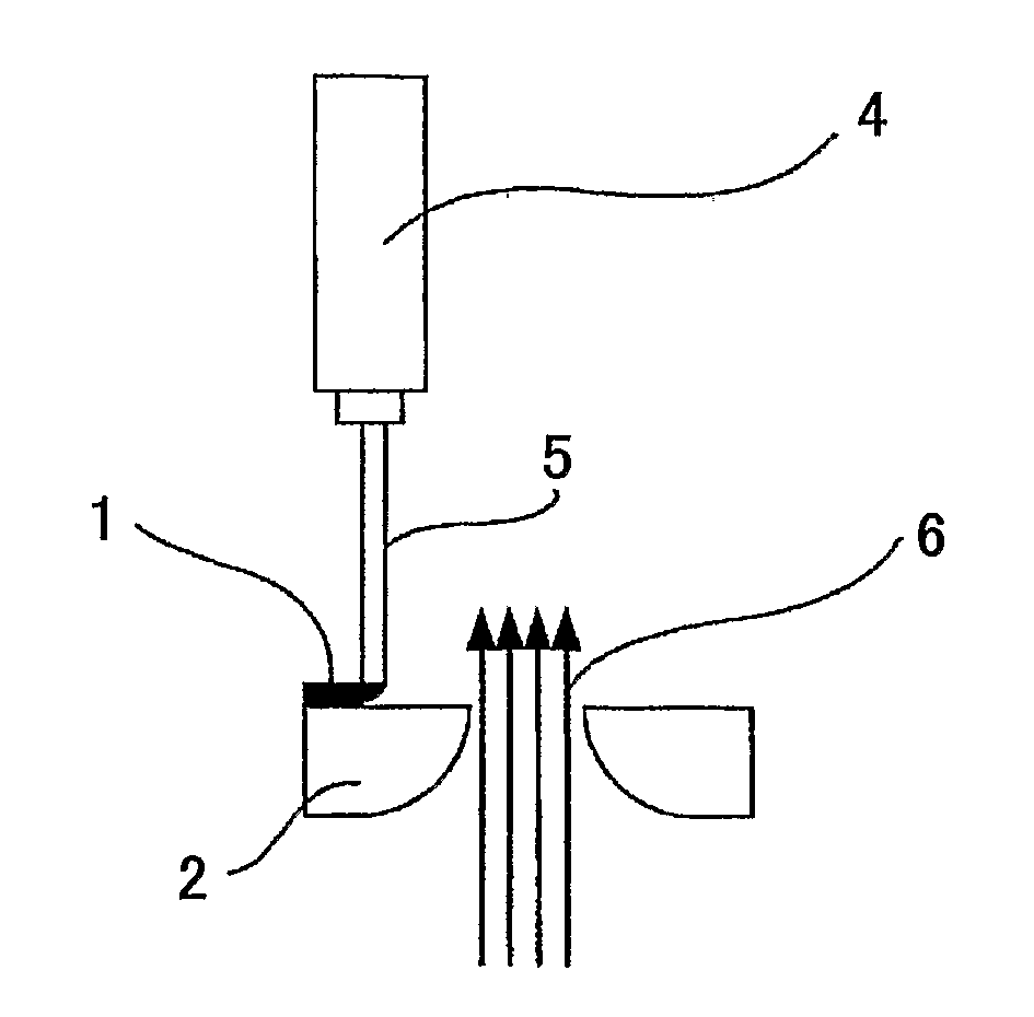
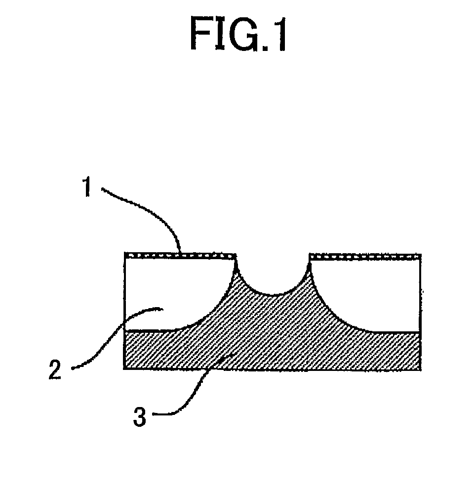
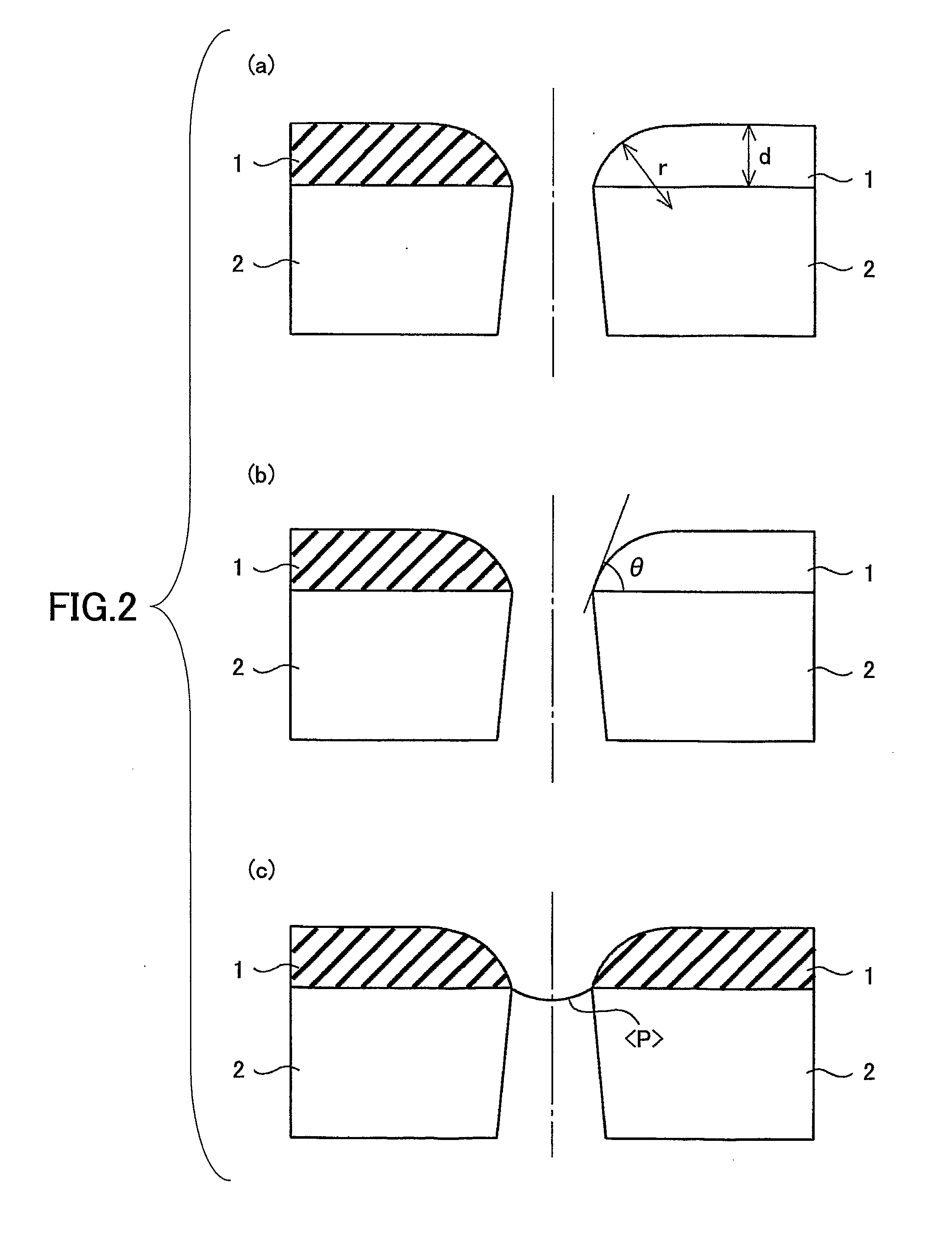
A recording method with an ink ejected by an ink jet head, in which an ink repellent layer is formed on a surface of a nozzle plate of the ink jet head so that an opening portion for liquid ejections is established, the ink jet head being formed such that a cross-sectional area for the opening portion neighborhood of the ink repellent layer in a plane which is perpendicular to a centerline of the opening portion grows big sequentially as the cross-sectional area is further separated from the surface of the base material nozzle plate, wherein the amount of the ink transferred onto a recording medium during a contact time of 100 ms measured by a dynamic scanning absorptometer with environmental conditions of temperature 23° C. and relative humidity 50% RH is between 4 and 15 ml / m2, and the amount of the ink transferred onto the recording medium during a contact time of 400 ms measured by the dynamic scanning absorptometer with the environmental conditions of temperature 23° C. and relative humidity 50% RH is between 7 and 20 ml / m2.

Description

TECHNICAL FIELD[0001]The invention relates to a recording method which records imaging information into a recording medium using an ink jet recording method and printed matter.BACKGROUND ART[0002]Conventionally, as an image forming apparatus such as a printer, a facsimile, a copying machine, and a plotter, for example, there is an ink jet recording apparatus which forms images by ink. In such an ink jet recording apparatus, ink-repellent film is formed on a surface of the ink ejection side of an ink jet head because the image formation is performed by ejecting inks from a nozzle member.[0003]Concerning such an ink jet head, in patent document 1, a processing method for forming an ink-repellent thin film by plasma polymerization with silicone oil is described and a nozzle plate of the ink jet head having the ink-repellent thin film thereof is described.[0004]Also, in the invention of the patent document 2, after an ink-repellent film which is polymerized in fluoric resin or which is ...

Claims


Application Information

Patent Timeline
IPC IPC(8): B41J29/393B41J2/01B41J2/135B41J2/14B41J2/16B41M5/00B41M5/50B41M5/52C09D11/00
CPCB41M5/00C09D11/32B41J2002/14475B41J2/1433B41J2/1606C09D11/40B41J2/01B41M5/50B41M5/52
Inventor MORI, TAKASHI
Owner RICOH KK
Learn More