Flexible laminate having thermoplastic polyimide layer and method for manufacturing the same

a technology of thermoplastic polyimide and flexible laminate, which is applied in the direction of thermoplastic polymer dielectrics, dielectric characteristics, synthetic resin layered products, etc., can solve the problems of low heat resistance, high dielectric constant, and inability to directly laminate on copper layers, etc., to achieve excellent heat resistance, electrical properties, and mechanical strength. , the effect of easy manufacturing

Inactive Publication Date: 2009-02-05
KURASHIKI BOSEKI KK +1
View PDF7 Cites 61 Cited by
  • Summary
  • Abstract
  • Description
  • Claims
  • Application Information

AI Technical Summary

Benefits of technology

[0012]The present invention has been made to solve the above-mentioned problems of the conventional technology and has a main object to provide a flexible laminate containing a metal foil layer / a thermoplastic polyimide layer or / and a conductor circuit layer / a thermoplastic polyimide layer, which can be easily manufactured by a laminating method and has such characteristics inherent in polyimide as excellent heat resistance, electrical properties, and mechanical strength.
[0013]A further object of the present invention is to provide a flexible laminate containing a metal foil layer / a thermoplastic polyimide layer or / and a conductor circuit layer / a thermoplastic polyimide layer, which can be easily manufactured by a laminating method and excels in various properties such as dimensional stability and resistance to soldering heat besides such characteristics inherent in polyimide as excellent heat resistance, electrical properties, and mechanical strength.
[0014]Another object of the present invention is to provide a method which is capable of laminating a polyimide layer on a conductor layer (a metal foil) by heating a thermoplastic polyimide resin film under pressure and thus manufacturing the above-mentioned flexible laminate with high productivity at a low cost by the laminating method without using an adhesive.

Problems solved by technology

However, since an adhesive is used, there are such problems that its dielectric constant becomes high and heat resistance becomes low.
However, since a thermosetting polyimide film does not melt by heating, it cannot be directly laminated on a copper layer.
However, every method has drawbacks.
Specifically, in the two-layer board having a copper layer formed on the surface of a polyimide resin film by the use of the vacuum deposition process, it poses such problems as poor adhesion of the copper layer to the polyimide resin film and low resistance to migration.
On the other hand, since the casting method requires the steps of applying a polyamic acid which is a precursor of polyimide onto a copper foil and imidizing the polyamic acid at an elevated temperature, it has such drawbacks that the impurities may be easily intermingled with the material and the voids and such defective curling as warp of the produced board may easily occur, besides the complicated production steps and inferior productivity.
Accordingly, it is also difficult to put this method in practical use.
However, these methods pose such problems that a copper layer formed by electroless copper plating also exhibits insufficient adhesion to a polyimide resin film, the peel strength (tearing off strength) of the copper layer is low, and thus the obtained board is inferior in reliability.
Further, another drawback common to all methods mentioned above is the fact that the laminating on a conductor layer can be performed only one side by one side, and a plurality of working steps are needed for laminating on both sides.
However, the conventional polyimide is not suitable for melt fabrication even if it is thermoplastic.
Accordingly, such a method also poses the problems that a dielectric constant becomes high due to the use of an adhesive as mentioned above and the heat resistance becomes low.

Method used


Image

  • Flexible laminate having thermoplastic polyimide layer and method for manufacturing the same
  • Flexible laminate having thermoplastic polyimide layer and method for manufacturing the same
  • Flexible laminate having thermoplastic polyimide layer and method for manufacturing the same

Examples


production example 1

of Thermoplastic Polyimide Resin Film:

[0120]A used resin pellet contained a thermoplastic polyimide having the chemical constitutional formulas represented by the aforementioned formulas (6) and (7) (AURUM (registered trademark) PD500A manufactured by Mitsui Chemicals, Inc.; Tg: 258 [° C.], melting point: 380 [° C.], melt viscosity measured at the shear rate of 500 sec−1:700 [Pa·S]) and a thermoplastic polyimide having the chemical constitutional formula represented by the aforementioned formula (6) (AURUM (registered trademark) PD450C manufactured by Mitsui Chemicals, Inc.; Tg: 250 [° C.], melting point: 388 [° C.], melt viscosity measured at the shear rate of 500 sec−1:500 [Pa·S]) in the ratio of 90:10. The melt viscosity [Pa·S] of the thermoplastic polyimide resin used for extrusion molding was measured using a flow tester CFT-500 manufactured by Shimadzu Corporation according to JIS K-7199.

[0121]The above-mentioned resin pellets were dried at 180° C. for 10 hours in a hot-air ty...

production example 2

of Thermoplastic Polyimide Resin Film:

[0122]A thermoplastic polyimide resin film (hereinafter referred to as “thermoplastic PI film b”) of 50 μm thickness was obtained by following the same procedure and the corona discharge treatment as in Production Example 1 of Thermoplastic Polyimide Resin Film mentioned above, except that the resin pellet containing a thermoplastic polyimide having the chemical constitutional formulas represented by the aforementioned formulas (6) and (7) (AURUM (registered trademark) PD500A manufactured by Mitsui Chemicals, Inc.; Tg: 258 [° C.], melting point: 380 [° C.], melt viscosity measured at the shear rate of 500 sec−1:700 [Pa·S]) and a polyetherimide resin having the chemical constitutional formula represented by the aforementioned formula (13) (ULTEM (registered trademark) 1000P manufactured by General Electric Company) in the ratio of 90:10 was used.

Polyimide Resin Film:

[0123]Since the polyimide having the chemical constitutional formula represented ...

example 1

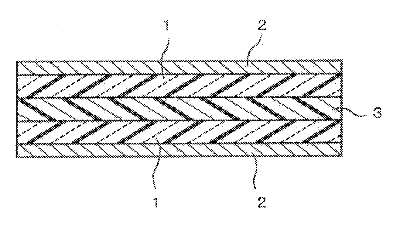
[0124]Copper foils of 18 μm thickness were respectively superposed on both sides of the thermoplastic PI film “a” of 50 μm thickness. They were sandwiched between stainless steel plates (hereinafter referred to as “SUS plate”) from both sides. Further, two sheets of Fujilon STM manufactured by FUJICO Co., Ltd. as a felt-like cushioning material made of polybenzoxazol were respectively superposed on outer opposite sides of the SUS plates, and they were set in a vacuum hot pressing machine manufactured by KITAGAWA SEIKI Co., Ltd. Thereafter, the inside pressure of the pressing machine was reduced to 1.0 kPa, the temperature was increased to 300° C. at the rate of temperature increase of 5° C. / min. under pressure of the initial pressure of 10 kgf / cm2, then the pressure was raised to the secondary-forming pressure of 25 kgf / cm2, and this state was held for 10 minutes. Thereafter, the pressing machine was cooled slowly to room temperature to obtain a flexible double-sided copper-clad lam...


PUM

PropertyMeasurementUnit
Tgaaaaaaaaaa
melting pointaaaaaaaaaa
glass transition temperature Tgaaaaaaaaaa

Abstract

In a flexible laminate containing a metal foil layer / a thermoplastic polyimide layer or / and a conductor circuit layer / a thermoplastic polyimide layer, the metal foil layer or the conductor circuit layer is bonded to at least one side of the thermoplastic polyimide layer. The thermoplastic polyimide layer is formed from a thermoplastic polyimide resin film or sheet produced by melt extrusion of a thermoplastic polyimide resin. Alternatively, the thermoplastic polyimide layer is formed from a biaxially oriented thermoplastic polyimide resin film or sheet. Such a flexible laminate can be easily manufactured by a lamination method which comprises bonding a thermoplastic polyimide resin film (1) to a metal foil (2) or a conductive circuit layer (4) by heating under pressure, and has excellent heat resistance, electrical properties and mechanical strength inherent in a polyimide. When the biaxially oriented thermoplastic polyimide resin film or sheet is used, the flexible laminate can be improved in dimensional stability and resistance to soldering heat.

Description

CROSS-REFERENCE TO RELATED APPLICATIONS[0001]This is a continuation of Application PCT / JP2007 / 056218, filed Mar. 26, 2007, which was published under PCT Article 21(2).BACKGROUND OF THE INVENTION[0002]1. Field of the Invention[0003]This invention relates to a flexible laminate having a thermoplastic polyimide layer as an adhesive layer and a method for manufacturing the same.[0004]2. Description of the Prior Art[0005]In recent years, in view of high densification of the printed circuit boards in electronic devices, the printed circuit boards used therein are advanced toward the multi-layer construction and the flexible circuit boards of the multi-layer structure are widely used.[0006]Since a polyimide resin film is enrich in flexibility, is soft and also excels in various characteristics, such as the mechanical strength, heat resistance, and electrical properties, it has been heretofore widely used as a three-layer board containing copper foils laminated thereon by the use of an adhe...

Claims


Application Information

Patent Timeline
Patent Type & Authority Applications(United States)
IPC IPC(8): B32B15/088
CPCB32B15/08B32B2307/518B32B2038/0028B32B2311/00B32B2379/08C08G73/1039C08G73/1042C08G73/105C08G73/1064C08G73/1071H05K1/0346H05K1/036H05K3/4635H05K3/4655H05K2201/0129H05K2201/0154H05K2201/068H05K2203/065B32B27/281B32B2307/202B32B37/04Y10T428/31681B29C65/02B32B15/088C08G73/10
Inventor NISHIKAWA, TAKAHIRONAKANO, MASASHIAKANE, NORIYUKIITO, NOBUHITOSASAKI, MASAKIARIMA, MASAO
Owner KURASHIKI BOSEKI KK
Why Eureka
Try Eureka