
Optical element comprising restrained asymmetrical diffuser

Inactive Publication Date: 2009-02-12
SKC HAAS DISPLAY FILMS CO LTD
View PDF6 Cites 34 Cited by
  • Summary
  • Abstract
  • Description
  • Claims
  • Application Information

AI Technical Summary

Benefits of technology

[0070]The enhanced asymmetric diffuser of this invention may contain materials, additives, components, blends, coatings, treatments, layers or regions that provide additional optical, mechanical, environmental, thermal or electrical benefits. The properties of the diffuser film may include one or more of the following: Optical: increased optical throughput, increased / decreased diffusion along one or more axis, reduced or increased birefringence, increased luminance uniformity, improved color stability, reduced haze; Mechanical / Physical: increase rigidity, reduced thickness, reduced weight, increased scratch resistance, reduced / increased pencil hardness, anti-blocking features; Environment: reduced warpage, increased light resistance, increased moisture resistance, increased light resistance, increased ultraviolet absorption; Thermal: increased thermal resistance, increased softening temperature; Electrical: decreased surface resistance.

Problems solved by technology

Such an illumination profile is not desirable, and so a diffuser plate is used to smooth the illumination profile at the back of the LCD device.
Handling of these individual light management films to manufacture LCD displays is very labor intensive as some films are supplied with protective cover sheets which must be first removed and then each light management film placed in the back light unit of the LCD individually.
Also, inventory and tracking of each film individually can add to the total cost to manufacture the LCD display.
Further, as these light management films are handled individually there is more risk of damage to the films during the assembly process.
These plates are thick and heavy while display manufacturers are always trying to thin the form factor and reduce the weight of displays.
The diffuser plates often deform or warp after exposure to the elevated humidity and high temperature caused by the lamps which causes viewing defects in the displays.
In addition, the diffuser plates require customized extrusion compounding to distribute the diffusing particles uniformly throughout the polymer matrix, which further increases costs.
Here, the use of adhesives to laminate these layers together results in reduced efficiency of the system by adding light absorption materials.
Also the additional processing cost to laminate the layers together is self-defeating.
Also, this previous disclosure does not solve the issue of the thick form factor and heavy weight of the diffuser plate.
Nor does this solution address the issue of warping of the diffuser plate.
These special lamination techniques which laminate around the perimeter of the adjacent layers requiring an air gap that is costly and generally not effective at maintaining physical integrity of the light management arrangement.

Method used


Image

  • Optical element comprising restrained asymmetrical diffuser
  • Optical element comprising restrained asymmetrical diffuser
  • Optical element comprising restrained asymmetrical diffuser

Examples


example

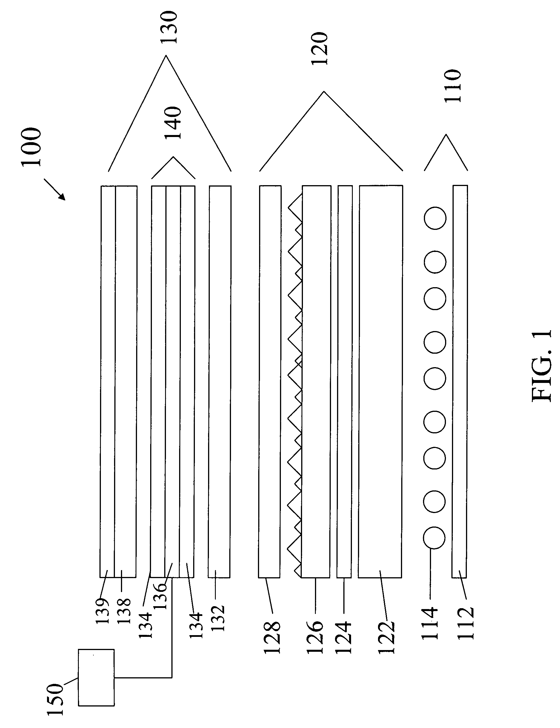
[0115]In order to demonstrate a preferred embodiment of the present invention a commercial LCD TV was procured. The TV chosen was a 42″ LG Philips LCD TV, model 42LB5D. The LC panel and the arrangement of light management films was removed from the TV exposing an array of CCFLs in the backlight unit. A conventional 1.5 mm slab diffuser (from 42″ LG Philips TV) was installed over the CCFLs. Then a conventional 200 um bead coated collimating diffuser (bottom diffuser from 42″ LG Phillips TV) was placed over the slab diffuser. Next, a conventional prismatic collimation film(from 42″ LG. Philips TV) was placed over the bead coated collimation film. Finally, a conventional 200 um bead coated collimating diffuser (top diffuser from 42″ LG Philips TV) was placed over the prismatic collimating film.

[0116]The optical performance of the backlight only was then tested for Luminance to compare to the subsequent stack-up using the present invention.

[0117]The light management films were again rem...


PUM


Abstract

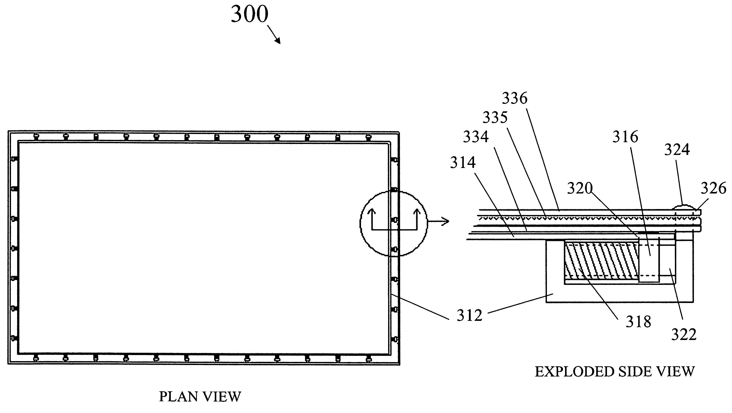
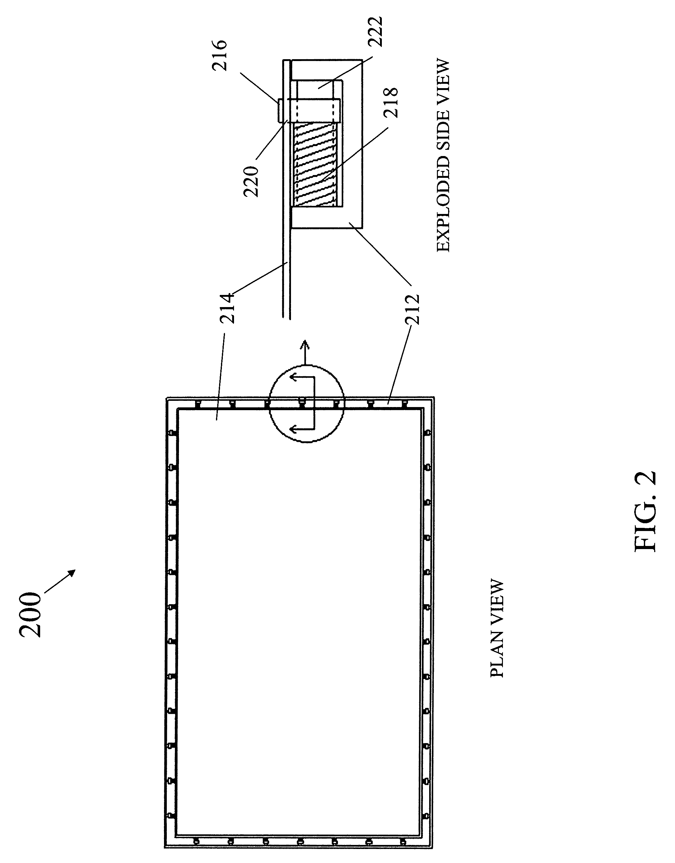
The present invention provides an optical element having an optical film, the optical element comprising a support frame having a shaft therein, the support frame being provided around a perimeter of the optical element and the optical film having slots on a periphery thereon, the periphery of the optical film being provided on the support frame. The invention further provides a pin provided in each of the slots and protruding into the support frame and slidable on the shaft by a controlled tensile force and a spring mechanism that is slidable on the shaft for providing the controlled tensile force to the optical film, wherein the optical film is an asymmetric diffuser.

Description

BACKGROUND OF THE INVENTION[0001]The invention relates to a unitary optical element including an asymmetric diffuser and its use in optical displays, and more particularly to liquid crystal displays (LCDs) that may be used in LCD monitors and LCD televisions.[0002]Liquid crystal displays (LCDs) are optical displays used in devices such as laptop computers, hand-held calculators, digital watches and televisions. Some LCDs include a light source that is located to the side of the display, with a light guide positioned to guide the light from the light source to the back of the LCD panel. Other LCDs, for example some LCD monitors and LCD televisions (LCD-TVs), are directly illuminated using a number of light sources positioned behind the LCD panel. This arrangement is increasingly common with larger displays, because the light power requirements, to achieve a certain level of display brightness, increase with the square of the display size, whereas the available real estate for locatin...

Claims


Application Information

Patent Timeline
IPC IPC(8): F21V17/10
CPCG02B5/0242G02B5/0257G02B6/0051G02B5/0289G02B5/045G02B5/0278G02B5/02G02F1/1335
Inventor LANEY, THOMAS M.
Owner SKC HAAS DISPLAY FILMS CO LTD
Learn More