
Method and apparatus for generation and amplification of light in a semi-guiding high aspect ratio core fiber

a technology of semi-guiding and high aspect ratio, applied in the field of laser systems, can solve the problems of reducing beam quality, poor optical quality, and scaling laser output power, and achieve the effects of high aspect ratio cross-section, high beam quality, and high slow-axis beam quality

Active Publication Date: 2009-02-12
RAYTHEON CO
View PDF27 Cites 65 Cited by
  • Summary
  • Abstract
  • Description
  • Claims
  • Application Information

AI Technical Summary

Benefits of technology

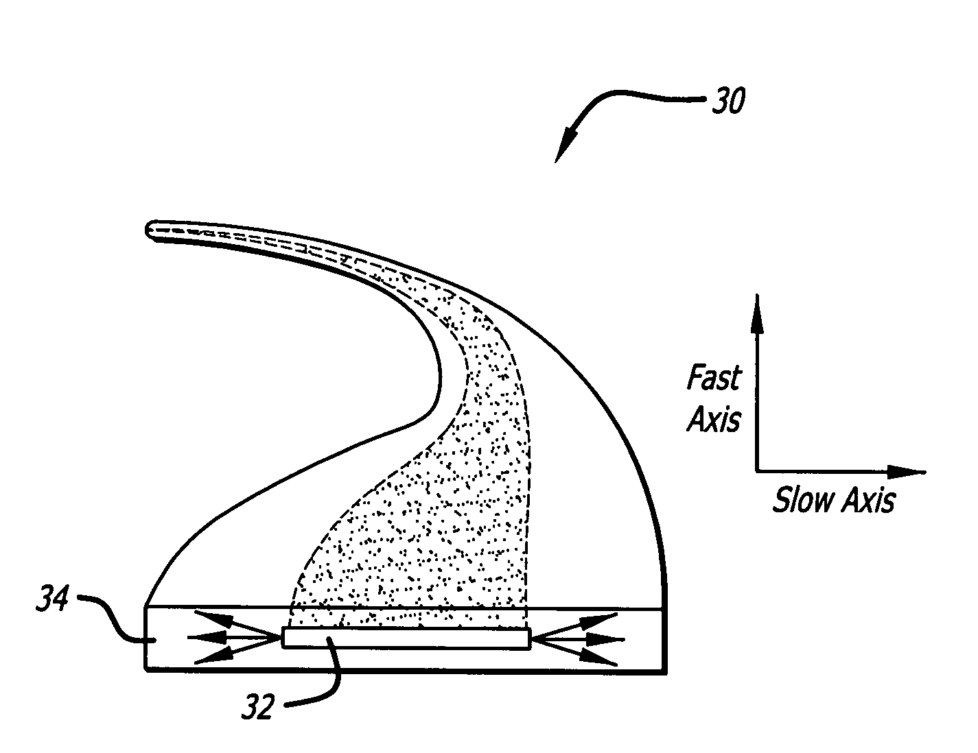
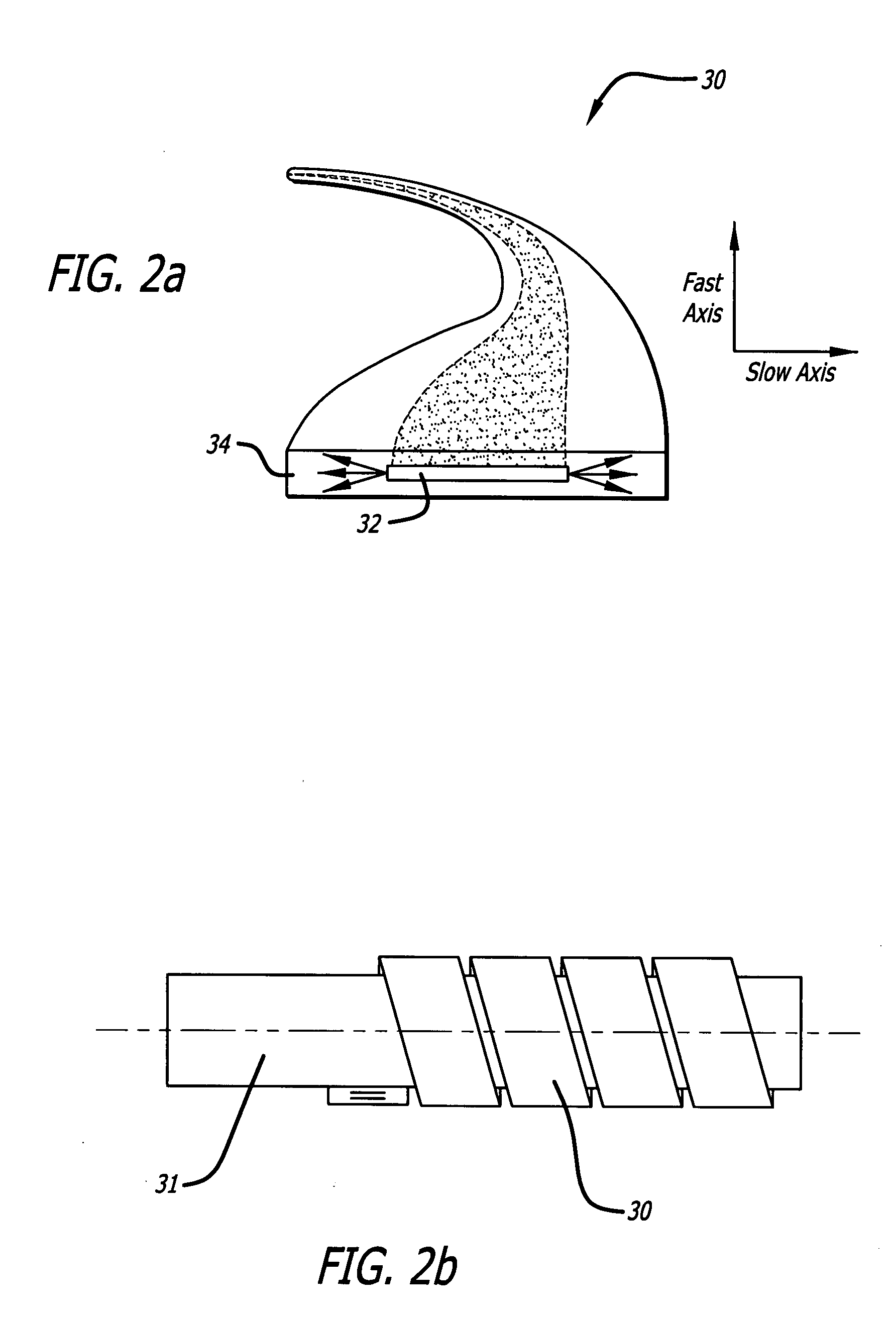
[0015]The need in the art is addressed by the laser gain medium and laser system of the present invention. The novel laser gain medium includes an active core having a high aspect ratio cross-section with a fast axis and a slow axis, claddings adapted to provide waveguiding by means of total internal reflection at the fast-axis boundaries of the core, and a material adapted to avoid waveguiding by minimizing reflections at the slow-axis boundaries of the core (the fast-axis direction is across the thin dimension of the core, while the slow-axis direction is along the wide dimension of the core). In an illustrative embodiment, the laser gain medium is an optical fiber. The core and claddings form a waveguide adapted to control modes propagating in the fast-axis direction. When the laser gain medium is employed as a laser oscillator, a high reflectivity mirror and an outcoupler are positioned at opposite ends of the core to form a laser resonator adapted to control modes in the slow-axis direction. When the laser gain medium is employed as a laser amplifier, a high slow-axis beam quality of the output beam is achieved by, first, injecting an input signal beam that has a high beam quality, and second, exploiting gain guiding to preserve the high beam quality even in the presence of imperfect homogeneity of the fiber gain medium.

Problems solved by technology

The challenges in scaling lasers to higher energy and power are often similar, but not always so.
One of the most challenging problems for scaling laser output power has proven to be beam quality reduction, which arises from the increased cross-sectional area of the active medium, as well as from thermal effects, optical damage, and nonlinear processes that are initiated in the laser materials at high optical intensities.
Large size crystals, however, suffer from poor optical quality, and are expensive to manufacture.
This factor limits the power scalability of crystalline bulk systems.
Cooling bulk glass elements is complicated, however, because of the low thermal conductivity of glass.
In addition, fiber designs are compact, flexible, and lightweight.
On the other hand, the small cross-sectional area of fibers, which is advantageous for beam quality, heat dissipation, and gain saturation, becomes a real problem if one wishes to scale the output power to higher levels.
Optical damage and nonlinear optical effects both arise at high light intensity.
So, when attempting to increase laser output while maintaining high beam quality (BQ), the dilemma of choosing between bulk crystal or glass active elements and fiber gain elements has not yet been resolved.
Considering the specific case of fiber-based lasers and amplifiers, the applicability of traditional active fibers for building high-energy laser and long distance lidar / ladar sources is limited.
However, if the core is too small, optical damage can preclude reliable operation.
Thermal damage of pump combiners represents another challenge.
However, the increased core size cannot generally be made to operate only in a single mode, because the numerical aperture (NA) required for single-mode operation at large core sizes is lower than can be reliably achieved.
Another problem with the low-NA fibers is that they are sensitive to bending, and this fact complicates packaging.
Few solutions have been proposed that can scale the output power of individual fiber lasers to this level.
However, maintaining a high beam quality and achieving a high combining efficiency (which means that the total combined power is equal to the sum of the powers of the individual fibers) have proven to be a challenge when addressing high power lasers.
In spite of extended efforts, fiber combining schemes have never reached the power levels achieved by direct LMA fiber sources.
Nonlinear optical, thermal, and gain-saturation affects have so far limited the output power of fiber-combining schemes to a level that is nearly an order of magnitude below that possible with LMA designs.
This suggests that fiber combining methods may not be capable of meeting the requirements of the intended applications.
An analysis of the present state of the art suggests that existing methods of raising fiber-laser output powers (either singly or combination) above 10 to 20 kilowatts are not capable of also delivering a high output beam quality.

Method used


Image

  • Method and apparatus for generation and amplification of light in a semi-guiding high aspect ratio core fiber
  • Method and apparatus for generation and amplification of light in a semi-guiding high aspect ratio core fiber
  • Method and apparatus for generation and amplification of light in a semi-guiding high aspect ratio core fiber

Examples


Embodiment Construction

[0029]Illustrative embodiments and exemplary applications will now be described with reference to the accompanying drawings to disclose the advantageous teachings of the present invention.

[0030]While the present invention is described herein with reference to illustrative embodiments for particular applications, it should be understood that the invention is not limited thereto. Those having ordinary skill in the art and access to the teachings provided herein will recognize additional modifications, applications, and embodiments within the scope thereof and additional fields in which the present invention would be of significant utility.

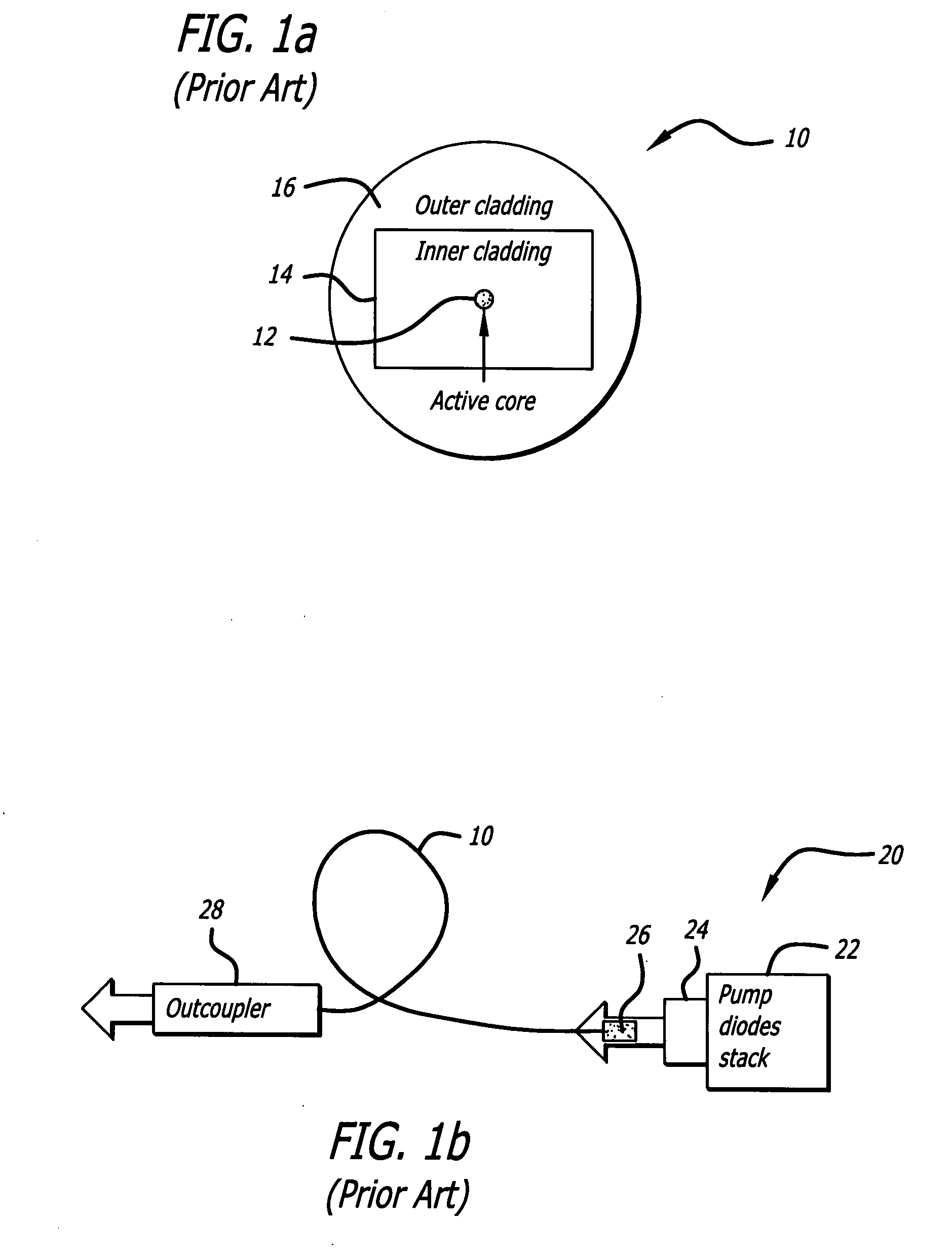
[0031]FIG. 1a is a simplified schematic of a conventional cladding-pumped active fiber 10. Active fibers are typically manufactured in a double-clad configuration, having a small round core 12 capable of propagating a single mode or perhaps a few modes. The core 12 is surrounded by two claddings: an inner cladding 14 that directly surrounds the core ...


PUM

PropertyMeasurementUnit
diameteraaaaaaaaaa
poweraaaaaaaaaa
poweraaaaaaaaaa

Abstract

A planar laser gain medium and laser system. The novel laser gain medium includes an active core having a high aspect ratio cross-section with a fast-axis dimension and a slow-axis dimension, signal claddings adapted to form reflective boundaries at fast-axis boundaries of the core, and a material adapted to minimize reflections at slow-axis boundaries of the core. In an illustrative embodiment, the laser gain medium is an optical fiber. The core and claddings form a waveguide adapted to control modes propagating in the fast-axis direction. When the laser gain medium is employed as a laser oscillator, a high reflectivity mirror and an outcoupler are positioned at opposite ends of the core to form a laser resonator adapted to control modes in the slow-axis direction.

Description

BACKGROUND OF THE INVENTION[0001]1. Field of the Invention[0002]The present invention relates to laser systems. More specifically, the present invention relates to systems and methods for generating and amplifying laser energy.[0003]2. Description of the Related Art[0004]High energy and high power laser systems generate optical beams for applications such as laser weapons, industrial lasers for materials processing, and long range lidar / ladar systems. (Energy and power are related, but fundamentally different, physical parameters. The challenges in scaling lasers to higher energy and power are often similar, but not always so. The present invention can be adapted to either energy or power scaling. Throughout the remainder of this discussion, the term power will be used with the understanding that this invention can also be used to increase energy.) One of the most challenging problems for scaling laser output power has proven to be beam quality reduction, which arises from the incre...

Claims


Application Information

Patent Timeline
Patent Type & Authority Applications(United States)
IPC IPC(8): H01S3/063G02B6/036C03B37/07G02B6/26
CPCH01S3/06704H01S3/06708H01S3/06729H01S3/094019
Inventor SHKUNOV, VLADIMIR V.BETIN, ALEXANDER A.ROCKWELL, DAVID A.
Owner RAYTHEON CO
Learn More