
Multi-tube fuel reformer with augmented heat transfer

a fuel reformer and multi-tube technology, applied in electrochemical generators, sustainable manufacturing/processing, electrochemical generators, etc., can solve the problems of poor heat transfer, poor washcoat adhesion, and prior art fuel reformers such as catalytic partial oxidation (cpox) reformers have limitations in maximum obtainable reforming efficiency, etc., to achieve excellent mechanical stability of washcoat, excellent heat transfer, and excellent heat transfer

Inactive Publication Date: 2009-02-12
DELPHI TECH INC
View PDF4 Cites 11 Cited by
  • Summary
  • Abstract
  • Description
  • Claims
  • Application Information

AI Technical Summary

Benefits of technology

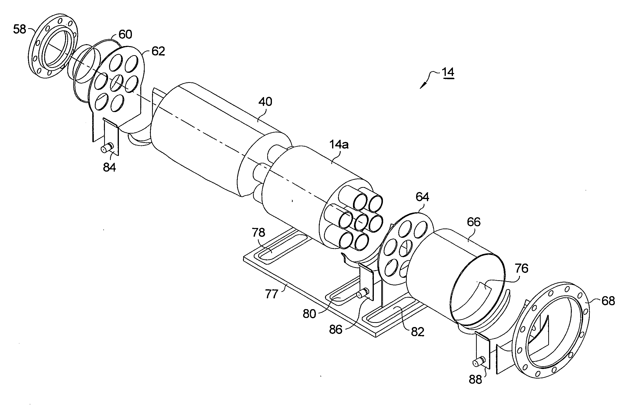
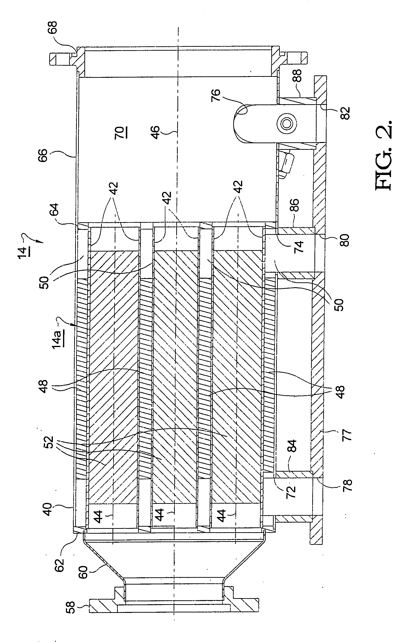
[0009]A catalytic reformer assembly includes a reactor comprising a plurality of parallel tubes arranged within a tubular housing. A metal substrate, formed as corrugated sheet metal, rolled wire mesh, wire gauze, or preferably a metal foam lattice, is attached as by brazing to the parallel tubes on both their inside and outside surfaces. A catalytic washcoat is applied to the metal substrate within the tubes, defining thereby the interiors of the tubes as catalytic reforming reactors. The endothermic reforming reactions within the tubes are supported by heat from hot combustor exhaust gas flowing around the tubes in contact with the augmenting heat transfer metal substrates outside the tubes. Radial temperature gradients are small because of excellent heat transfer across the tube walls, resulting in excellent mechanical stability of the washcoat on the metal substrate. Preferably, the tubes are formed of Inconel 625 and the metal substrate is formed of Fecralloy®, a high temperature alloy having excellent thermal conductivity and oxidation resistance.

Problems solved by technology

Prior art fuel reformers such as catalytic partial oxidation (CPOx) reformers have limitations in maximum obtainable reforming efficiency.
Such reactors have shown maldistribution of heat and poor washcoat adhesion.
During coating of the washcoat slurry onto the reactor surfaces, only small amounts of washcoat are picked up; the washcoat cannot be controlled as to where and how much of it will be deposited; and thermal differential expansion (TDE) of the base metal of the reactor and of the washcoat can cause the washcoat to spall off within a few minutes of the start of operation.
Prior art microchannel planar reactors are complex and expensive to design and fabricate; cannot be repaired after failure; and are susceptible to thermal imbalance and washcoat spalling.

Method used


Image

  • Multi-tube fuel reformer with augmented heat transfer
  • Multi-tube fuel reformer with augmented heat transfer
  • Multi-tube fuel reformer with augmented heat transfer

Examples


Embodiment Construction

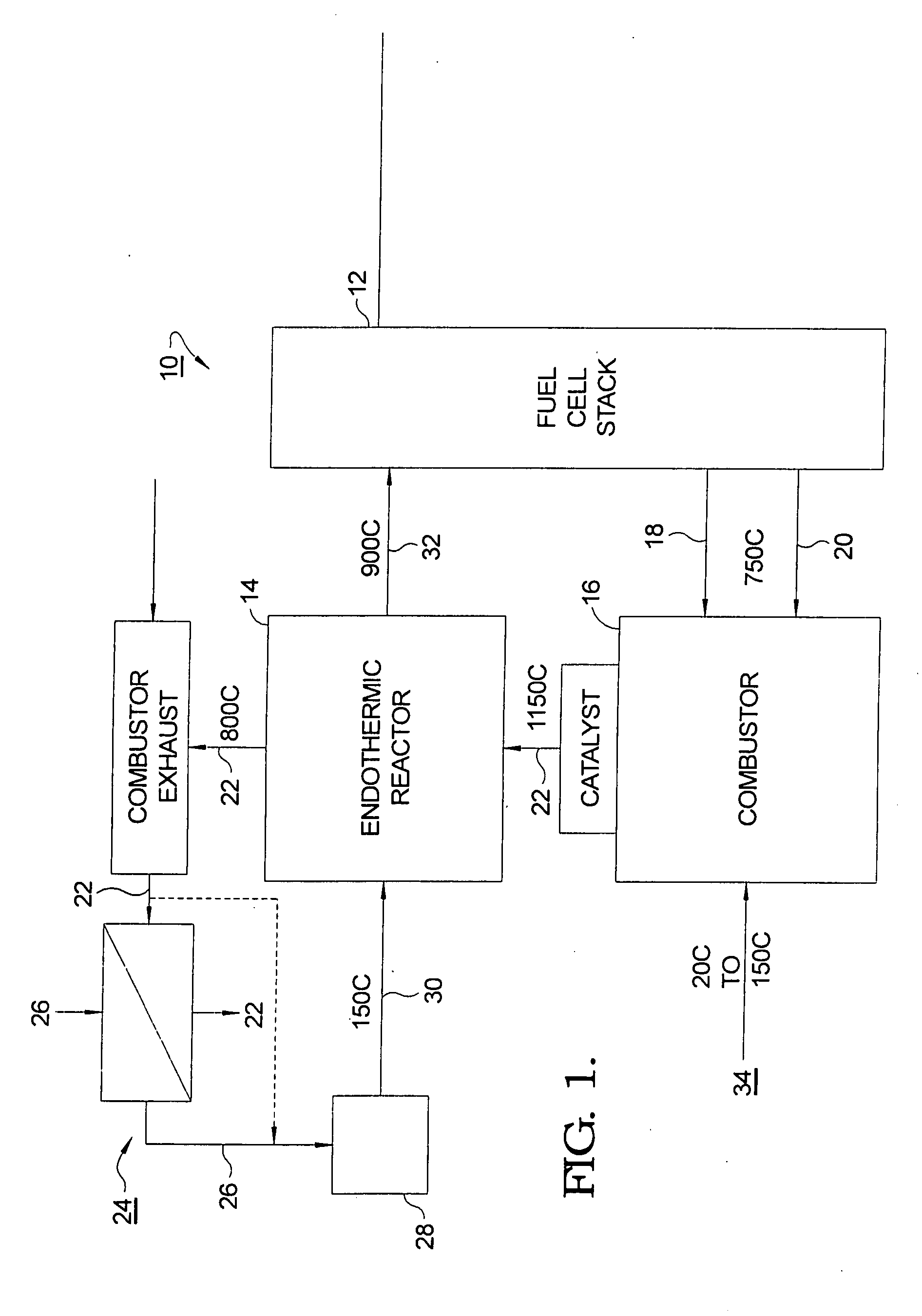
[0019]Referring to FIG. 1, a schematic drawing of a fuel cell system 10 employing endothermic fuel reforming in accordance with the invention includes a fuel cell stack 12, for example, a solid oxide fuel cell stack; an endothermic reforming reactor 14; a combustor 16 for burning tail gases 18 (anode) and 20 (cathode) from stack 12 to produce a combustor exhaust 22; and heat exchanger 24 for vaporizing incoming fuel 26 to be mixed with air, steam, and recycled anode tail gas 28.

[0020]In operation, incoming fuel 26 is vaporized by heat exchanged from combustor exhaust 22 either before or after being mixed with air, steam, and recycled anode tail gas 28. The flows of air, steam, and recycled anode tail gas are individually controlled and variable, as is known in the prior art of endothermic reforming. The resulting fuel stream 30, typically at a temperature of about 150° C., is fed to endothermic reactor 14 wherein reformate 32 is produced and supplied to stack 12 at a temperature of ...


PUM


Abstract

A catalytic reformer assembly including a reactor comprising a plurality of parallel tubes arranged within a tubular housing. A metal substrate, formed preferably as a metal foam lattice, is brazed to the tubes on both their inside and outside surfaces. A catalytic washcoat is applied to the metal substrate within the tubes, defining thereby the tubes as individual catalytic reforming reactors. Endothermic reforming reactions within the tubes are supported by heat from hot combustor exhaust flowing around the tubes in contact with the augmenting heat transfer metal substrates outside the tubes. Radial temperature gradients are small because of excellent heat transfer across the tube walls, resulting in excellent mechanical stability of the washcoat on the metal substrate. Preferably, the tubes are formed of Inconel 625 and the metal substrate is formed of Fecralloy®, a high temperature alloy having excellent thermal conductivity and oxidation resistance.

Description

TECHNICAL FIELD[0001]The present invention relates to catalytic hydrocarbon fuel reformers for converting a hydrocarbon stream to a gaseous reformate fuel stream comprising hydrogen; more particularly, to fuel reformers having heat exchange capability; and most particularly to a multi-tube endothermic fuel reformer having a high surface area metal substrate attached to both the insides and the outsides of the reforming tubes to augment heat transfer to the reforming catalyst. The present invention is useful for providing reformate as a fuel to a fuel cell, especially a solid oxide fuel cell, or to an internal combustion engine.BACKGROUND OF THE INVENTION[0002]A catalytic hydrocarbon fuel reformer containing a fuel reforming catalytic reactor converts a fuel stream comprising, for example, natural gas, light distillates, methanol, propane, naphtha, kerosene, gasoline, diesel fuel, or combinations thereof, and air, into a hydrogen-rich reformate fuel stream comprising a gaseous blend ...

Claims


Application Information

Patent Timeline
IPC IPC(8): H01M8/18
CPCB01J8/067Y02E60/525B01J2208/00309B01J2208/00504B01J2208/00522B01J2219/00099B01J2219/00117B01J2219/00157C01B3/384C01B2203/0233C01B2203/066C01B2203/0822C01B2203/1082C01B2203/1247C01B2203/1294C01B2203/148H01M8/04022H01M8/0618H01M2008/1293Y02E60/50B01J12/007Y02P20/10
Inventor FISCHER, BERNHARD A.ENGLAND, DIANE M.RANELLI, DAVID J.
Owner DELPHI TECH INC
Learn More