
Electron beam recording apparatus

a recording apparatus and beam technology, applied in the field of electroctron beam recording apparatus, can solve the problems of low recording resolution of information signals to be recorded, low recording accuracy of master disk tracks, and high density recording, and achieve high positional accuracy, high positional accuracy, and high accuracy

Inactive Publication Date: 2009-03-05
RICOH KK +1
View PDF19 Cites 8 Cited by
  • Summary
  • Abstract
  • Description
  • Claims
  • Application Information

AI Technical Summary

Benefits of technology

[0024]The present invention aims to provide an electron beam recording apparatus capable of recording information by irradiating an electron beam onto a predetermined position of a sample with high positional accuracy.
[0026]According to an aspect of the present invention, the electron beam recording apparatus can perform the convergence position control of the electron beam with high accuracy by calculating a displacement of the convergence position of the electron beam with respect to the sample due to the magnetic field on the irradiation axis. Therefore, the electron beam is irradiated onto a predetermined position of the sample with high positional accuracy for recording the information. Moreover, since the electron beam is irradiated onto a predetermined position of the sample with high positional accuracy, printing on the surface of the sample can be performed with high shape accuracy.
[0027]According to another aspect of the present invention, in the electron beam recording apparatus, since focal position displacement of the electron beam with respect to the sample due to the magnetic field on the irradiation axis is experimentally calculated based on focal position adjustment information obtained when a focal position is adjusted with respect to particles on the surface of a test substrate, focal position control of the electron beam can be performed with high accuracy. Therefore, the electron beam is irradiated onto a predetermined position of the sample with high positional accuracy for recording the information. Moreover, since the electron beam is irradiated onto a predetermined position of the sample with high positional accuracy, printing on the surface of the sample can be performed with high shape accuracy. Furthermore, since the displacement of the convergence position is experimentally computed using the test substrate with the particle on the surface, the electron beam recording apparatus is simple and inexpensive.
[0028]According to still another aspect of the present invention, in the electron beam recording apparatus, since an irradiation position displacement of the electron beam with respect to the sample due to the magnetic field on the irradiation axis is experimentally calculated based on irradiation position adjustment information obtained when an irradiation position is adjusted with respect to particles on the surface of a test substrate, irradiation position control of the electron beam can be performed with high accuracy in addition to the focal position control of the electron beam. Therefore, the electron beam is irradiated onto a predetermined position of the sample with higher positional accuracy for recording the information. Moreover, since the electron beam is irradiated onto a predetermined position of the sample with higher positional accuracy, printing on the surface of the sample can be performed with higher shape accuracy.
[0029]According to a further aspect of the present invention, since the convergence position adjusting part includes an electrostatic lens, the electron beam recording apparatus can perform convergence position adjustment (focal position) adjustment with high responsivity and can perform printing (recording) with high shape accuracy even when driven at high speed.

Problems solved by technology

A problem with such a master disk cutting process using a visible light or an ultraviolet laser light is that the recording resolution of information signals to be recorded is limited due to limitations of a light spot diameter, resulting in preventing high density recording.
This lowers accuracy of the track pitch of master disks or causes reproduction jitter.
Referring back to the magnetic shield device disclosed in Patent Document 1, although the cancel coil needs to be highly accurately mounted, it is difficult to accurately mount the Helmholtz coil because of its relatively large size.
If the Helmholtz coil is not formed in an ideal shape, the magnetic field generated by the Helmholtz coil is not uniform, resulting in lowering of device accuracy.
Moreover, a facility using the magnetic shield device of Patent Document 1 is large and expensive.
Referring to the information recorder of Patent document 2, the electromagnetic motor includes a rotating part, and hence it is difficult to completely shield magnetism of the entire electromagnetic motor by surrounding the entire electromagnetic motor with the magnetic casing (high permeability material).
Another problem with the information recorder disclosed in Patent Document 2 is that, if a large amount of high permeability material is used, the weight of the rotating unit is increased.
Still another problem with the information recorder of Patent Document 2 is that, if a magnetic shield for the entire device is also provided, a magnetic field is generated in the direction of the electron beam irradiation axis in a magnetic shield opening of the irradiating unit and an opening of the magnetic casing of the rotating unit.
The generated magnetic field affects the electron beam, which prevents accurate correction of a focal point and results in lowering of exposure quality.
Accordingly, the electron beam irradiation device of Patent Document 3 cannot accurately correct the focal point, and therefore exposure quality is lowered.
However, since there are many constraints on workability and structure such as ventilation and air conditioning facility, this configuration is not so effective for variation of a magnetic field generated inside the shielded device.
Furthermore, since the entire device is magnetically shielded, the electron beam irradiation device is large and expensive.

Method used


Image

  • Electron beam recording apparatus
  • Electron beam recording apparatus
  • Electron beam recording apparatus

Examples


first embodiment

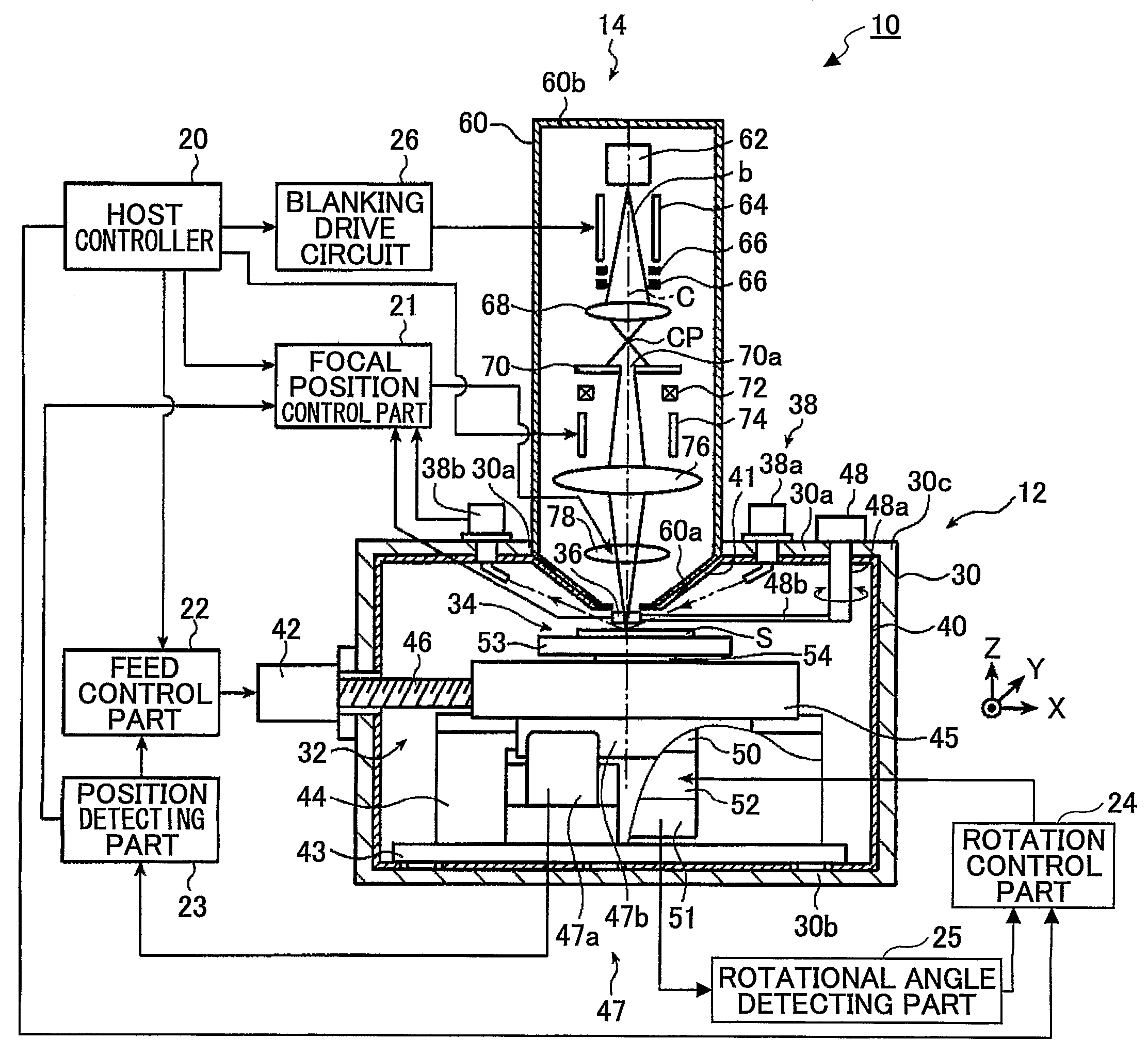
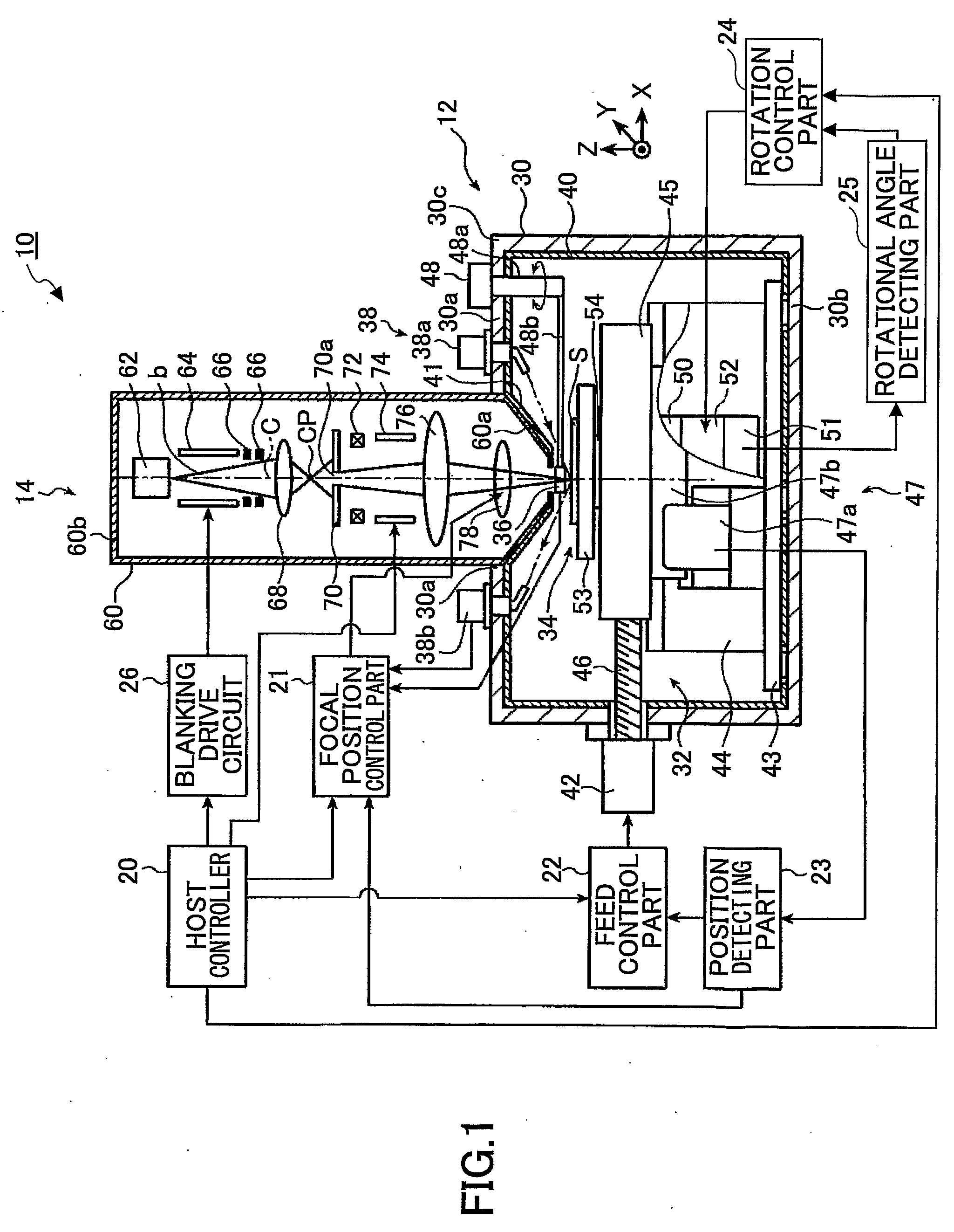
[0048]In the following, an electron beam recording apparatus according to the present invention is described with reference to the accompanying drawings. FIG. 1 is a schematic diagram showing an electron beam recording apparatus 10 according to the present invention.

[0049]The electron beam recording apparatus 10 is used, for example, for producing an optical disk master by printing a pattern on a glass substrate.

[0050]The electron beam recording apparatus 10 includes a printing part 12, an electron beam generator 14, a host controller 20, a focal position control part 21, a feed control part 22, a position detecting part 23, a rotation control part 24, and a rotational angle detecting part 25.

[0051]The host controller 20 is connected to and controls the focal position control part (convergence position control part) 21, the feed control part 22, and the rotation control part 24.

[0052]The host controller 20 is also connected to and controls, for example, an electron source 62 describ...

second embodiment

[0127]the present invention is described below.

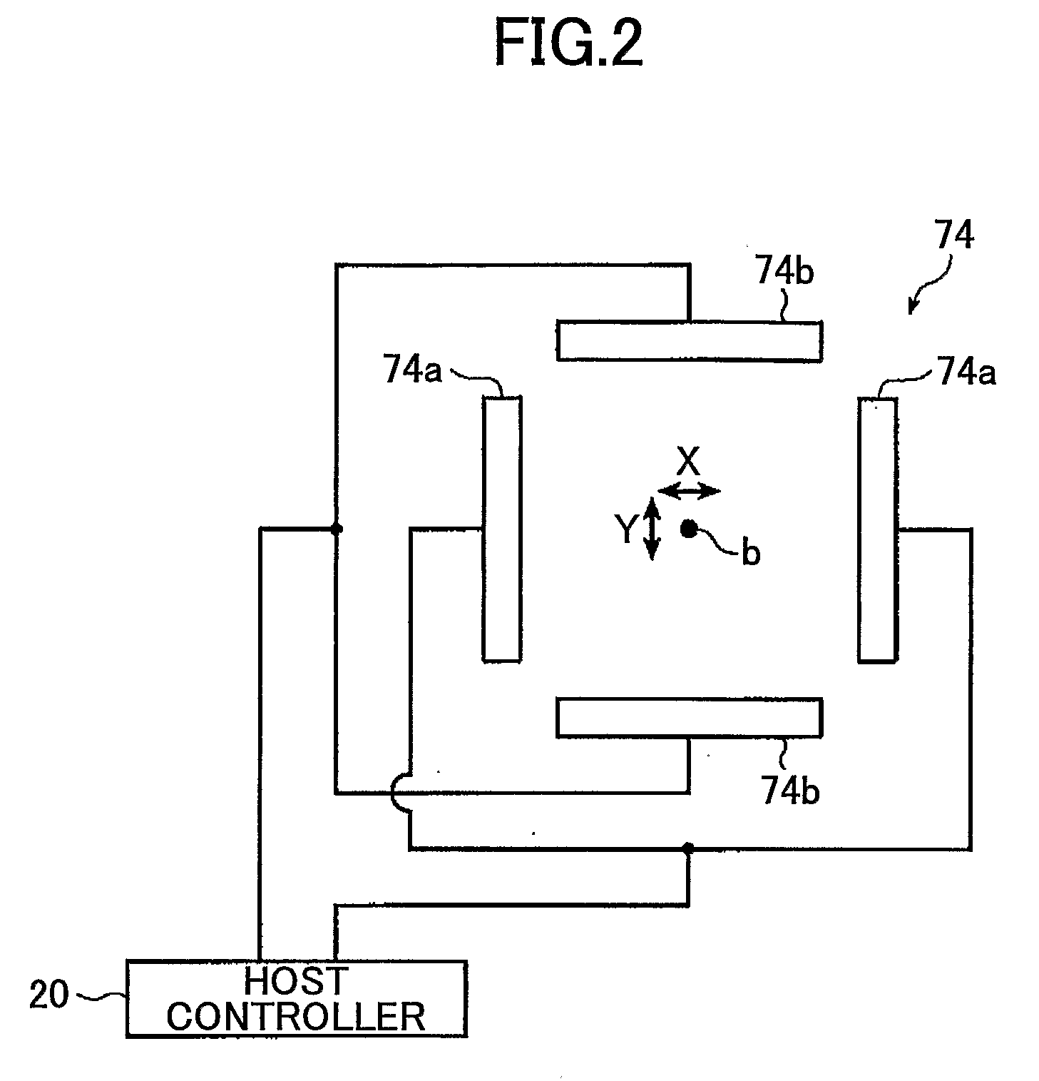
[0128]FIG. 9 is a schematic diagram showing an electron beam recording apparatus 10a according to the second embodiment of the present invention. FIG. 10 is a block diagram showing a structure of an irradiation position control part 100 of the electron beam recording apparatus 10a according to the second embodiment of the present invention. FIG. 11 is a schematic diagram showing a structure of an electrostatic deflection electrode 74 of the electron beam recording apparatus according to the second embodiment of the present invention. Component parts of the electron beam recording apparatus 10a identical to those of the electron beam recording apparatus 10 of the first embodiment of the present invention shown in FIGS. 1 through 8 are denoted by the same reference numerals and are not described in detail.

[0129]The electron beam recording apparatus 10a of the second embodiment is different from the electron beam recording apparatus 10 (se...


PUM

PropertyMeasurementUnit
diameteraaaaaaaaaa
magneticaaaaaaaaaa
magnetic detectoraaaaaaaaaa

Abstract

An electron beam recording apparatus is disclosed that records information onto the surface of a sample by using an electron beam. The electron beam recording apparatus includes an electron source that irradiates the electron beam, a magnetic detector that is configured to move onto and out of an irradiation axis and acquires magnetic information on the irradiation axis, a convergence position control part that calculates a convergence position correction amount for correcting a convergence position of the electron beam with respect to the surface of the sample based on the magnetic information, and a convergence position adjusting part that adjusts the convergence position of the electron beam with respect to the surface of the sample. The convergence position control part causes the convergence position adjusting part to adjust the convergence position of the electron beam with respect to the surface of the sample based on the convergence position correction amount.

Description

TECHNICAL FIELD[0001]The present invention relates to an electron beam recording apparatus that records information by irradiating an electron beam onto a predetermined position, and particularly relates to an electron beam recording apparatus used for producing a master of optical disks by printing a pattern with an electron beam.BACKGROUND ART[0002]In recent years, there has been a growing demand for accuracy improvement of microfabrication technology such as exposure technology for master optical disks and semiconductor technology. For example, optical disks are fabricated through a master disk production process for producing a stamper from a glass plate and a disk production process for producing optical disks with use of an injection mold with the stamper mounted thereon.[0003]In a typical master disk production process, a master disk production machine emits a visible light, an ultraviolet laser light, or the like from the light source in an ambient atmosphere and focuses the...

Claims


Application Information

Patent Timeline
Patent Type & Authority Applications(United States)
IPC IPC(8): G11B9/00
CPCG11B7/261G11B11/03G11B9/10G11B7/26H01J37/147H01J37/21H01J37/30
Inventor OBARA, TAKASHIMIYAZAKI, TAKESHI
Owner RICOH KK
Learn More